Does anyone know these cards ?
I've got one here trying to make it work. I've reflowed the little extra board that had bad solder joints, and one of the chips needed replacement.
When inseretd in an apple II, all according to the documentation ; the computer boots as usual. When trying to activate it with PR#? (I don't remember the number now) nothing special happens
I don't see a picture and I don't see a signal at the oscilloscope
This is difficult to debug because it's nearly impossible to probe when inserted in a A2
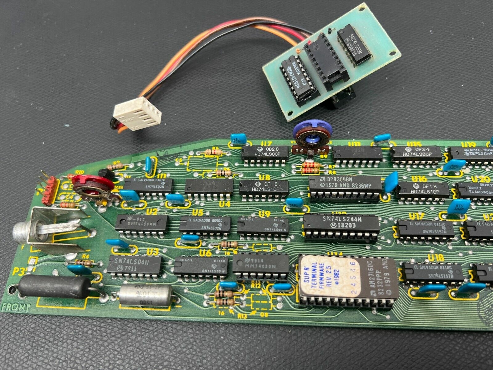
The big black resistor (lower left) seem to be hot to the touch which I find weird.
Apart from the carpet bombing approach of desoldering ALL 20+ ttl logic chips, putting them all on sockets, and testing them all, I don't see how I could debug this thing.
Is it common ? I mean is it worth the trouble ?
I have the exact same card with the exact same problem. It came with my Apple II+.
When I put it in slot 3 and type PR#3 it doesn't produce any signal. Not sure if the softswitch should be plugged in order to work - I have been trying it without it. The power resistor does heat up quite a lot, but I think this is normal.
80ColumnCard.png
Yes I'm afraid I may be doing something wrong,
So before either selling it or replacing all the chips (which may as well end up in disaster) i'd like to be sure I can actually use the thing.
What do you call the soft switch ?
The small board with the cable that you are supposed to plug between the chip on C2 and its socket.
Card documentation: click!
P.S. I just got it to work. The little board needs to be inserted. It doen't work without it.
Yeah I did use the chip, but for me it does not work
However your experience indicates that I could maybe, at least, concentrate my efforts on the little board
Hi,
I repaired a couple of 80 col videx cards, the problem was the same for both cards, lack of clock at pin 21 of the 46505 crt controller chip; without a clock, the crt controller does nothing. That COULD explain why you see a 40 col image but a black screen when the card switches to 80col mode.
Check that first.
Your card apparently must also be in solt #3 to work.
I would next check Q1 and that EPROM code is there and selectable.
https://www.silicon-ark.co.uk/datasheets/hd46505-datasheet-hitachi.pdf
Luca
Here is how I connected mine - the black cable is on top. The center socket of the small board should be empty:
IMG_5654.JPG
Btw, the small board is not a softswitch like I suggested above. It's just an adapter in order to get the clock signal, since the card doesn't have its own oscillator. The Videx cards do and they don't need to connect to the chip in C2. This one is really old school!
The M&R Sup'R'Term was as far as I know the first 80 column card for the Apple ][. The Videx card came out later and had a number of improvements like the clock signalling mentioned, and also the EPROM code. If I recall correctly you need to have some kind of driver loaded to run the Sup'R'Term.
It's a little bit too old school for my taste and I think I'll put it on eBay at some point where someone can appreciate it just for its age. I don't like how it touches the chips on the motherboard and this resistor heats up to almost 100°C, maybe more if the lid is closed. But the biggest disadvantage is the lack of a soft switch to automatically switch the monitor when the card is activated or deactivated. Instead it came with a hard switch that attaches to be back of the Apple II:
HardSwitch.JPG
Hi Luca,
I am trouble shooting a clone 80 column card now. I checked pin 21 as per your advice and I see about a 2Mhz clock at it. I am seeing a screen output but it's not recognizable, any other clues or suggestions?
Transistor Q1? Is that for the output signal, my guess is that it's working if I am seeing *some* output.
Regards
80 column card-2.jpg
80 column card-1.jpg
Can you buzz the little board for me, kinda where everything is going and leading pleaseeeee. unless you know somewhere i can find it .
Adrian just released a video on the subject: https://youtu.be/QZJGI62l65g
Ha great !
I didn't make any progress ; desoldering 20 chips just in the hope of fixing a card I don't really use is not something I fancy to do
Time to put my card again on sale on ebay :)
Surge2001 : I'll make pictures of it both sides and send it to you. It's a very simple design.
post the pictures here too if you can. if you can angle the camera to show the traces in between the legs on the bottom that would be great
IMG_7997.jpeg
SupRTerminalAdapter.jpg
There are no warranties with this diagram and I accept no responsibility for damage caused by using it, but Ive made every effort to validate the traces are correct for my Sup'R'Terminal adapter board, hope it helps someone.