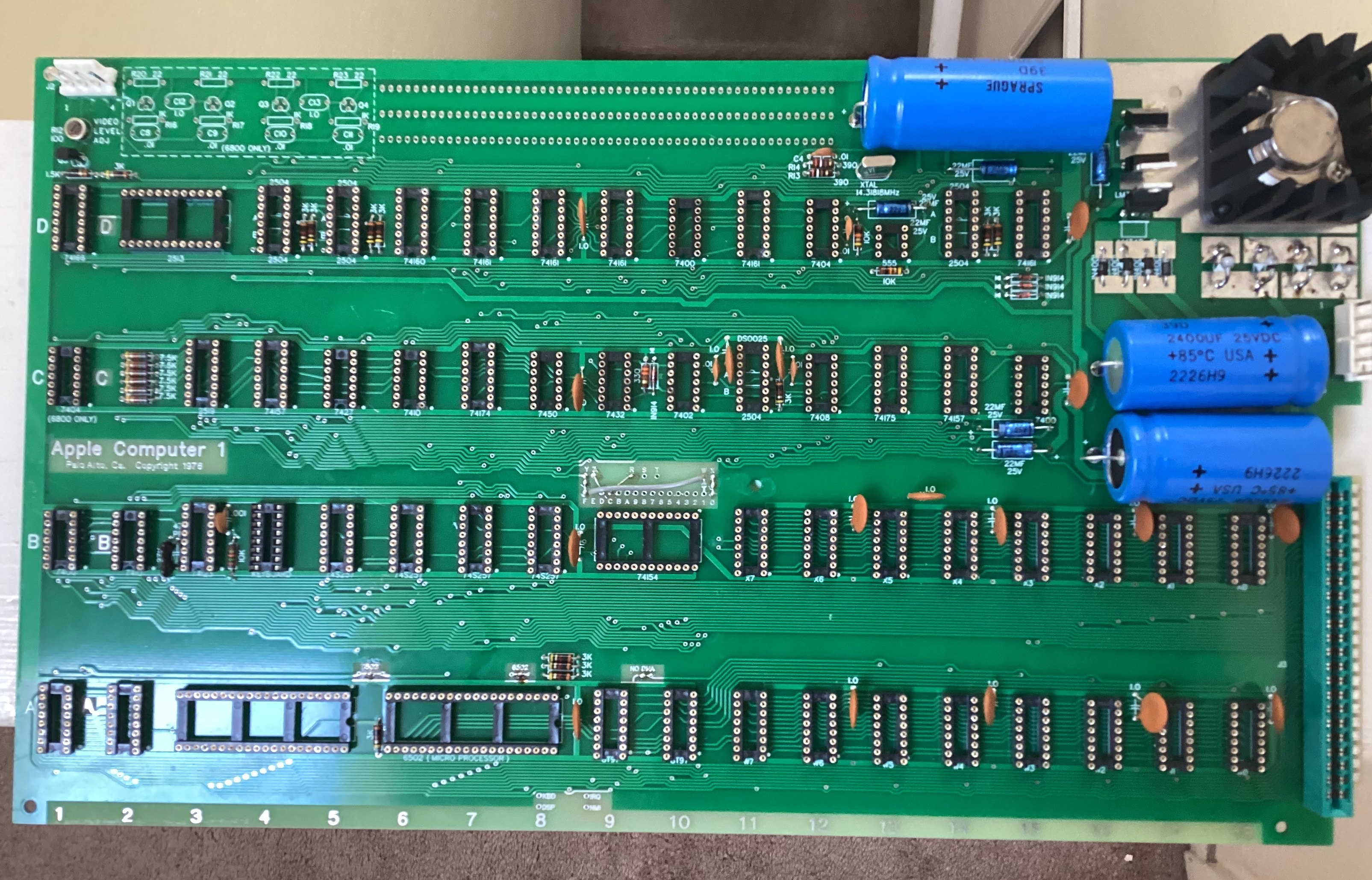
I've been building this thing for a while and just finished soldering the last of the components. But it would be nice if I got some confirmation that I haven't missed anything (or put anything in backwards).
Note: I haven't added any reliability mods to this yet as I want to see how this thing works in as close to the original configuration as I can get it. I'll likely tweak it over time as I work out the kinks.
But before I do that, I want to make a power supply and check all the voltages on the board. Once I'm sure that's right, my plan is to follow the 8-bit Guy's approach. Populate the terminal side and make sure that's working before moving on to the Computer.
Hi, great job!
Everything seems fine, the diodes and voltage regulators in the upper right corner are oriented correctly. Just in case, make sure that the pins of the LM323k go through the holes in the heatsink do not contact it.
In post #1, DistantStar001 wrote:
"Once I'm sure that's right, my plan is to follow the 8-bit Guy's approach. Populate the terminal side and make sure that's working before moving on to the Computer. "
Uncle Bernie warns:
If you do that half-baked IC population approach, you invite trouble, as some of the control inputs to the terminal section are floating and may lead to erratic behavior. The builders then whine and think the build does not work.
Once you have checked ALL the regulated supply rail voltages with empty sockets, there is ZERO risk in populating ALL of the ICs and then running the diagnostics page which is in the PROMs coming with my kits. But it is highly recommended to build the "gimmick switch" to avoid blowing up the PIA with wrongly applied loose wires for CLR SCREEN and RESET.
As for the "reliability mods", if your kit came with INTERSIL brand DRAMs, they typically only need the six 390 Ohm damping resistors. I have one build with INTERSIL which needed no reliability mods at first, but when I tried it months later, diagnostics spit out the occasional DRAM error. This went away after the six damping resistors were added.
I thought that everything has been outlined in the "Tips & Tricks" pdf --- maybe you did not get it ?
- Uncle Bernie
I think that not only the brand of DRAM chips, but also good quality 0.1uf capacitors are important for stable operation. I had one assembly, one of the first, DRAM Mostek 4027 in a plastic case, regular cheap resistors and mylar capacitors from aliexpress. When I bought the Allen Bradley resistors I assembled a new one and left this board for experimentation. I think everything new in the Apple-1 world in the last 3 years was tested on this board, including the Uncle Bernie reliability mod. I soldered those 6 resistors to the back side of the board, didn't notice any difference in performance and that was it, finding an explanation for myself that this mod is only needed for Intersil or Motorola chips.
After the embargo I understood that now it is very difficult to get the parts and I don't need the board "for experiments" anymore. In addition its cosmetic appearance after 3 years of experiments left much to be desired. I decided to take everything I could from it and transfer it to a new board, add more suitable Allen Bradley resistors and ceramic disk capacitors, and then sell it. I called it the Apple-1 replica Embargo Edition.
To my surprise after assembling it was as if the devil had entered into the board! It did not want to work steadily and did not pass the Mike Willegal memory test. I had another set of Mostek DRAM chips in a ceramic case, received as a gift from a very nice man and it worked fine. In the end I sorted out only 9 from 16 memory chips in plastic case, which worked with the new board without errors. Since I wasn't planning on parting with the ceramic DRAM kit, I put it all off for a while.
Soon I bought a cool vacuum tin plier and decided to get some ic sockets from the old board for my future projects. And when I saw Uncle Bernie's mod again I decided to try and move it to the Embargo Edition. The result exceeded all expectations, not only was I able to get all 16 Mostek in a plastic case back, but I also got 2 more working ICs out of the bag of previously rejected parts. Apparently my new disk capacitors were causing some kind of malfunction, luckily this effect was neutralized with this great mod. Otherwise I can not explain it, because all other parts except the resistors worked perfectly on the original board.
IMG_20230609_140122.jpg
IMG_20230609_133425.jpg
Good to know. I guess I can just go for broke and populate the whole thing when I'm ready. Although, I'm not too concerned with this behaving erraticaly with only half a board. My understanding of the 8-bit approach was to verrify that the terminal was generating a picture without risking the computer half of things. But if it's unnecessary, there's no point.
I am going to verify all voltages before I populate anything. But worry not. I have no intention of poking 5v into an open socket! The Commodore adaptor I bought has a clear screen and reset built in (and yes, I verified that they are correctly wired). But I can always add a gimmick switch to be extra safe.
Honestly, this is one of the things I intend to verify before I populate the ICs. I want to be sure that the connections are right. Especially with the keyboard! I made that mistake with an Apple II once. Never again!
As for the reliability mods... This is mostly for my own curiocity. Just how glitchy was it? Part of the fun of old machines is working within their limitations and learning their quirks.
However there is another reason for my delay. These mods need to be soldered to the back of the board, and for the moment, this board is free floating. and as careful as I intend to be, even living in a padded electrostatic bag, there is a chance that the mods could be knocked off. I do intend to make a proper case for this, but untill I do, I don't want anything hanging off the back of it.
Speaking of cases... What's the grounding story on these? I noticed that the back two standoff holes have grounding contacts, but most of the cases I've seen are made of wood or plastics. Should I bee looking to Earth ground?
In post #5, DistantStar001 wrote:
"As for the reliability mods... This is mostly for my own curiosity. Just how glitchy was it? Part of the fun of old machines is working within their limitations and learning their quirks."
Uncle Bernie answers:
Believe me, it ain't no fun to have an Apple-1 with a wonky DRAM. Without any 'reliability mods', the DRAM errors are rare (in most cases - there are addresses where it gets worse), but they may provoke random program crashes, and this is NOT acceptable. Look for the "Lisa Loop" story found in Tom Owad's book "Apple-1 Replica Creation - Back to the Garage" - she had one of the first Apple-1 originals and tried to teach BASIC to kids. The Apple-1 crashed / hang from time to time, frustrating the kids. Then reload the BASIC interpreter from cassette - with the original ACI which was wonky, too, all too often needing several retries. No checksum either - even more dubious. Interpreter could have been loaded faulty, another reason for random program crashes. Woz tried to fix Lisa's Apple-1 and she tells the story that he improved it a bit, but could never make it work reliably. When the Apple II came out, he gave one of the first production units to Lisa Loop so she could do her teaching of BASIC with a machine that really did work. Draw your own conclusions. My claim to fame is that I have fixed the Apple-1 and the ACI, so both finally work robustly, as it should have been from the beginning. Alas, I came 45 years too late.
As for the grounding, don't do it. The J1 connector has a "0v/GND" on pins #5 and #6, and you must connect the CT of the smaller transformer to it, BUT DO NOT CONNECT THE "GROUND" ON THE LINE CORD TO ANYTHING (unless you have a metal enclosure).
If you have a metal enclosure on any appliance which runs off the line voltage, the metal enclosure MUST be connected to the "ground" prong of the line plug. This is a safety rule applying to the whole world (UL, VDE, ...). The penalty for violations of this rule is death. (No joke !). However, make sure your electrical outlet has a proper "ground" and not a "phantom ground" where the "Neutral" wire is connected to the "ground" within the outlet --- this is illegal now, but older houses may still have that deadly contraption. In this case, if the "Neutral" wire breaks somewhere downstream, or gets high ohmic (i.e. due to corrosion of wire joints) then your nice metal enclosure will be "hot" and may electrocute you when you touch it.
So the best solution probably is to use a wooden or plastic enclosure and use a two prong line cord with no ground.
In case of any doubt, ask a certified electrician, an electrical engineer, or some other qualified professional. The 110 Vac in the USA may not be as deadly as the 220 Vac elsewhere (but it still may electrocute you). Avoid to tinker with line voltages unless you know what you are doing. Most professionals have had safety training and hence should know how to hook up an Apple-1 power supply to be safe and compliant with local electrical code.
- Uncle Bernie
I used Bernie's kit, just check voltages then put them all in and turn it on.
Also, mine has no reliability mods and has never crashed.