Thought I would show off my new toy and write a few things about the journey. Probably old news to many on here, but hey ho.
Apple-1 kit bought from Sir Uncle Bernie as the value of the kit is not only in the price (which, unless I wanted many frustrating hours of scouring surplus stores that everyone else has already scoured was much more expensive from elsewhere), but also in the reasonable certainty that the components had a high chance of actually working due to the testing performed before dispatch.
As I live in the UK with its 240V single phase live and neutral supply (which I spend all my working day generating), the choice of transformers was the first decision. Vintage Stancore units wern't attractive but the choice of new 240V compatible ones from Triad didn't quite look the part. However Triad still make the original specified units ie the F40-X and the F31-X which are at least 'authentic' even if I now have to have a 240/110V transformer that weights about 70lb just to power it.
PCB from our very own Retroplace_1 but with hard gold edge connector
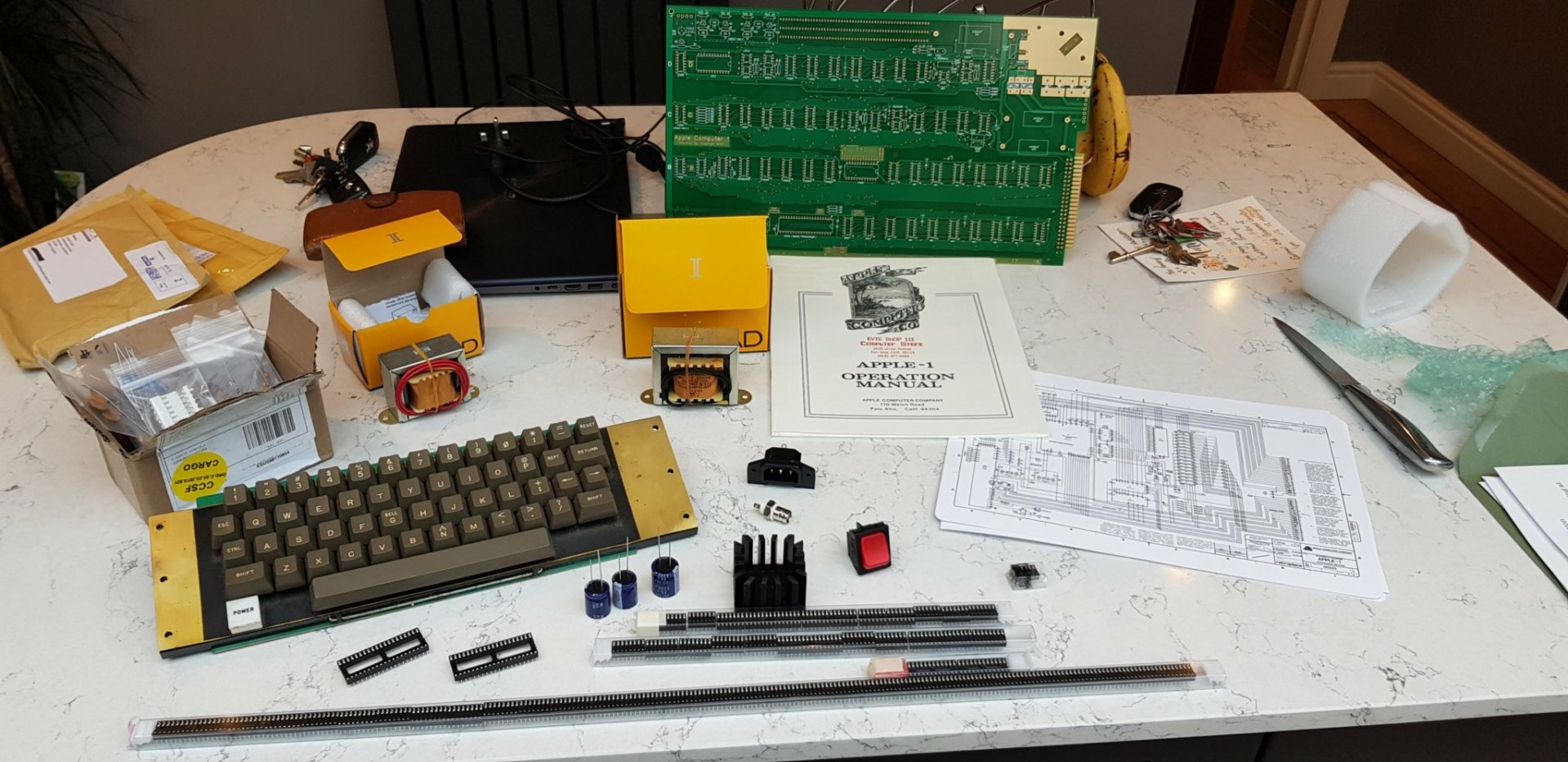
Keyboard is an Apple ][ RFI unit which I managed to find without an encoder, which was fine because I wanted to use the ⌘ Encoder ][ Plus replacement unit
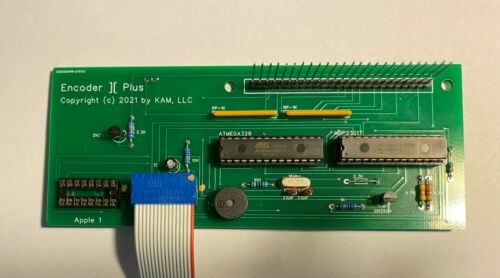
as this works really well with the Apple-1 as the clear screen is performed by Shift-Reset and Reset by CTRL-Reset without having to make any modification to the keyboard and as it sits nicely under the keyboard its not obvious or intrusive.
For IC sockets, I went for the stamped pin units from radio spares which seem to have a nice balance between 'vintage' look and reliability.
So, that was all the pieces gathered together. Next to actually build it.
:)
Awesome stuff, looking forward to your updates and progress!!
Big blue sprauges !
Mouser list them brand new ! 75-39D538G015JP6 and 75-39D248G025JL6 but with a 25 week lead time. Ordered and the 5300uf due soon but the 2400uf wont be made until October. Ah well, some none original ones will do for now.
157 39D 5300uf brand new blue sprauges on stock at mouser now :)
First thing I did was make a base board to mount the PCB and the transformers on. This would give me a solid base to build from and also prevent/reduce the chance of putting a live PCB down on a screw head or a bit of cut of cable etc.
Apple-1 build 1.jpeg
Then it was onto fitting the IC sockets.
Because I had used the stamped pin units rather than the turned pin, it meant that I could insert them into the socket then bend over two pins in opposite corners to hold them in place. In this way, several sockets (or even all of them) could be mounted and then soldered in in batches. Because the tip of the iron was then nicely regulating and tinned, I could breeze through lots of connections one after the other.
Apple-1 build 2.jpeg
Koa is a none starter in the UK, so a bit of nice pine with suitable oak staining is the order of the day. I'm fairly useless at woodwork but its meant to look a bit home made, isn't it ?
Apple-1 build 3.jpeg
With a Microvax 3300 in the background.
The IC's in the kit are very nicely protected and are even arranged in rows and order so its a simple matter of getting the right row and slotting them in.
Fitting the chips.jpg
Complete circuit board.jpg
Case almost completed
Case1.jpg
Case2.jpg
Replaced the thick back panel with a much thinner panel to allow mounting of the sockets and recessed it as it looks nicer.
Finally, it lives
it works.jpg
The case however is useless at dissipating heat and the regulator got uncomfortably warm. A small quiet fan is the order of the day.
The keyboard is performing surprisingly well as I have previously had to strip one of these units down for repair, and they aint fun. Long strips of bendy and flimsy metal that break free from their mounting, however the encoder also includes an adjustable keyboard debounce feature which is nice on these old units.
The LCD is 22 years old but even then it still has difficulty with the sync and as such I have to overdrive the video signal a little to get it to work. An old monitor is next on the to find list.
Jobs to do
Fit fan
Sort out noisy ACI
Complete the front of the case
A Sanyo VM-4209 is daft money but managed to find one of these for pennies (not the actual one pictured, but the same make and condition)
Its a TV, but there is a circuit digram online to make a simple video buffer amp to connect the signal after the tuner so it should work and look the part, but for the price, even if I can't get it working its not cost anything.
Sony TV.jpg
In post #9, GaryC wrote:
"... here is a circuit diagram online to make a simple video buffer amp to connect the signal after the tuner"
Another Uncle Bernie tip:
follow the video signal downstream to the so-called "sound trap". You can also search upstream from the audio amplifier to find it, but there is a demodulator in between, so more work.
Cut the trace to the sound trap just before it, so the video signal does not see it.
But beware that some sound traps come in the form of a low pass filter for the video signal so it must pass through it, but this is a rare case.
Drawing a circuit diagram of the section between the IF and the video / audio amplifiers usually helps to identify the "sound trap".
Removing the "sound trap" greatly enhances the video bandwidth. Which the Apple-1 (and the Apple II) need ... 7 Mhz dot clock rate. This is juuust at the boundary of what you can see on a standard TV because the sound trap will dampen everything at the sound subcarrier frequency and above. Otherwise you could see the sound subcarrier in the picture.
Modifying cheap TVs was the only way back in the early 1970s to get an affordable B&W "monitor" for the early home computers. But avoid the "hot chassis" type: these may electrocute you or the poor Apple-1. Always double check that for any TV in question, the mains voltage inlet goes to a transformer primary and nowhere else. You best bet are small transistorized TVs which have a 12V plug for use in cars or campers or which have a battery compartment.
- Uncle Bernie
Yes, good advice
This unit can take a battery, but Sony also produced a monitor version that used exactly the same chassis and PCB but put an extra board with a simple amp to connect in place of the output from the decoder. As such I should just need to replicate that circuit and connect it where Sony did.
The LM323 gets a bit too hot so bought a small fan just to give an airflow past the heatsink as natural convection wasn't going to be enough
Got a small 40mmx40mm 24V DC Fan from RS and it fits nicely into the case.
20220712_192933.jpg
20220712_192946.jpg
And it gives just enough air flow to keep the regulator cool. I also put some vintage heatsinks on the To-220 regulators as I might as well have too much cooling as too little.
One really odd thing, the fan was specified as DC but refused to run on 1/2 wave rectified DC but runs perfectly well on 24V AC, which actually is perfect.
As my PC seems to have a line in for its sound input, I have put a trim pot instead of the 100ohm resistor to set the signal voltage between about 1.1V and 50mV as required.
20220712_192953.jpg
In post #12, GaryC wrote:
"One really odd thing, the fan was specified as DC but refused to run on 1/2 wave rectified DC but runs perfectly well on 24V AC, which actually is perfect."
Uncle Bernie warns:
Don't overstress a "DC" fan for 12Vdc with 24V. The reason why these don't work from a rectified AC without a filter cap is that they have electronics inside which generate a rotating magnetic field via a set of coils. This polyphase generator IC does not work below a certain voltage and this is what happens if you rectify AC and have no filter cap after the rectifier.
Some people have tried to run a small fan off the +12V regulated supply but this tends to make interference patterns on the screen.
So for a small DC fan it's probably best to tap into the unregulated supply on the 2400uF capacitors, and you could put some fat zener diode, fat resistor, etc. in series to bring the voltage at the fan down to 12V or so.
I never use fans myself for Apple-1 builds because the LM323K runs just fine even at +100deg C or more, and proper passive air flow design in an enclosure can get its temperature down to 70-80 deg C. There has been a lot of discussion about "proper" temperatures of ICs in the Apple-1 but unless a TTL starts smoking (put in backwards ?) or a regulator goes into thermal shutdown (they all have circuitry to protect themselves) there is no reason to install forced air cooling.
The reason for the fear of course is that people today are not used anymore to electronics which run hot. But back in the day, that was normal. Especially with tubes. Tube based TVs always were running so hot they were close to catch fire. But I have a TTL based digital clock which also as a lot of black soot inside its enclosure, on the surfaces.
Other than that, I really like this thread ... very few builders go into these details and show nice photos how to do it. I think this will inspire a lot of readers. Keep on the good work !
- Uncle Bernie
Cheers
Most of my time at work was maintaining Intel Multibus systems (8086 machines) and Honeywell DPS6 supermini computers (and I still use them as they remain to this day controlling the Nuclear Reactors I am now responsible for)
The Intel systems are notorious for failing if the fans fail, I also have a 80286 multibus machine at home and it has failed once due to lack of airflow. They really don't like the heat so I tend to be cautious.
The fan is odd, its a 24V DC unit and I put a 1/2 wave with a capacitor in at first but its running really nicely at the moment so not tempting fate but its nice to know the general IC's in an A1 are fairly heat tollerant.
So the Sony 9-90UB TV manual has this addon circuit
SonyCV90UBmod-1.jpg
And it connects into the video circuit here
Sony_TV9_90UB-6.jpg
Seems a perfect choice.
But where is the V & H sync ?
Think I need a better look ;)
Ok, so looking at the manual, the signal is taken to the sync circuit for separation just before Q503 so the circuit above is a little misleading because if the 'break here' is done before this signal is fed off, then it wont work.
Thought I would share this
First ever program running on my A1
First program1.jpg
First program2.jpg
Sorted out the PC's input and now using a proper MIC input so I can keep the 100ohm resistor so it saves as well as loads. I also realised that the noise on the ACI output made no sense. The signal to noise ratio from the output of the flipflop to the ACI output changed sbsolutley dramatically which is a bit daft given its just two resistors.
Doh, would have though years of calibrating neutron flux instruments at picoamps I would remember the basics of earth loops, SNR and scope use :) The 'noise' was actually down to measuring the signal with my scope which was on the 240 ring while my Apple-1 is after an old 5kVA 240/110V transformer and just measuring the gnd showed noise but its not actually significant with a battery operated recorder or laptop.
Now to get basic up and running.
Basic running.jpg
What is interesting, this machine seems really stable. While its only just getting going, its not locked up on me once.
What I would say to anyone thinking of the same journey, do it but just save your self a lot of hassle and get Uncle Bernies kit. Armins (Retroplace_1) PCB's work fine too.
Oh and get the sprauge capacitors from Mouser as soon as they are in stock (big ones there now, smaller ones in October) rather than pay the stupid Ebay prices for unknown condition units (but even then, they are expensive as they look like they are made to order in small numbers)
Oh, and keep scanning Ebay for an Apple ][ keyboard. You just might be lucky.
First big blue turned up today.
Big blue.jpg
Mouser do them to order and sell singles wherease most others want a bulk order. Still expensive though for a capacitor.
Playtime
20220811_204056.jpg
A very simple ROM card. No buffers but can take two 2732 EPROMS mapped by S & T on the motherboard. Makes BASIC a breeze to use.
Made a HASL one to check it works and might get a gold fingered version in the future. Put a couple of jumpers on to S & T so that I can either disable the chip, select it to S or T, or even run a jumper wire from the top connection of the jumper to one of the other mappings with a flying lead to the map area.
Connected up and it works :)
Awesome! Are you going to sell these or make it an open source project so people can build them for themselves?
Make it open source of course :) Will stick it on Github when I get chance
I do have 4 spares if anyone wants one in the UK ?
Cool... I'm in Texas so it would probably cost more to ship one here than for me to order 5 from JLCPCB... And probably easier to order from China as far as customs and other nonsense too.
Probably.
I do need to test it with both sockets filled first
Finished hacking up my simple EPROM card & internal riser
https://github.com/Gary-Clark/Apple-1
Allows two EPROMS to be mapped to the T & S chip select lines. I have BASIC in one and the Assembler in the other. I have also hacked up a none buffered riser card which allows me to run the EPROM card & the ACI at the same time within the case. Not tried it with three cards plugged in though.
Did you have any spare boards left you'd like to sell?
If so, let me know.... and thanks for sharing.
I have done a few minor tweaks and have a few on order that would be available when they turn up so PM me.
Damn
There is an error in the Apple manual
The first drawing with the connector pinout, has the T select line connected at pin 21 with S at pin 11 and R at pin L
However, in the circuit diagram it has T connected to L and R to 21 , so I have connected my chip select to R rather than T which is used by the ACI :(
Grr.
However, I made the chip select of the second EPROM run though a link so it could be disabled and also to allow a flying lead to the chip select connections. With this connected, I can now have the A1 assembler at 9000 and BASIC at 8000.
The riser also ran into a slight hitch, forgot that the big spraugs need clearance so the bottom slot of the three I wanted cant be used, but hey ho, I now have the ACI, BASIC and the A1 assembler inside the case.
Will do a few tweaks to the files then upload them to Github and anyone can have one of the spare cards as long as they understand they aren't perfect and were made just for fun :)
Gerbers finished and uploaded to Github https://github.com/Gary-Clark/Apple-1
Took a bit of time as I got side tracked into producing Gerbers for both of the Cromemco Dazzler's PCBs :) (they are also available within my repositry but have not yet been tested)
I'm definately going to have to build a few of those EPROM and 2 slot expanders!
Which fab did you use to make boards? JCLPCB or PCBWay? Can you share the info there so we can order easy or can we just zip up the gerbers from your github and upload them?
I got them done by JCL and the .rar files are in the repositry
https://github.com/Gary-Clark/Apple-1/blob/main/Apple-1%20EPROM/Gerber/Apple1%20EPROM.rar
https://github.com/Gary-Clark/Apple-1/blob/main/Apple-1%20riser/Gerber/Riser.rar
Perfect, thanks. I didn't know they would take rar files. I was scanning for .zip so I guess I missed them.
Boards came in today by DHL. That was pretty quick coming all the way from China.
One question on the EPROM card. The 1K resistor at R1... The box in the silk screening looks big... what rating should it be? 1/2 watt? a full watt? I only have 1/4 watt on hand, I guess I will have to order some bigger ones.
Can you upload the EPROM images? Or provide a pointer where to find them? I've got an EPROM programmer and a bunch of 2732 chips...
Oh also... what is your suggested configuration of the two jumpers on the card?
I'm guessing maybe the images I'm looking for can be found here:
https://mirrors.apple2.org.za/ftp.apple.asimov.net/images/apple1/
But I'm not sure if "apple1basic.bin" can just be written directly to the 2732. I'm thinking the assembler you are talking to may be the one in "Apple 1-Assembler_V1.0.zip" but I am not sure which .BIN in a1asm is the right one to use. There are a bunch of them in the zip file for different addresses.
1/4 watt resistor, It was Kicad that seemed to decide it needed a big box :)
If both roms are in, both jumpers should be made to map them to select lines S & T. Then jumper S & T to 9000 and E000 on the Apple-1 PCB (first remove the jumper between W & E000 and make it from W to 1000 to give RAM from 0000 to 1FFF)
The jumpers also mean you can map the EPROM whereever you like. For example, you could put a wire from the EPROM side of the jumper to the select line map area of the Apple-1 rather than use the S & T lines on the bus.
I used these files. The assembler is built to operate at 9000 and of course Basic at E000. They are in Intel Hex because thats what my programmer likes.
Thanks! Greatly appreciated!
Looks like I'm going to have to write a Perl script to convert that Intel Hex to a true binary, which is what the TL866 II+ programmer I use needs.
If you don't want to script it, find a burner program that supports both formats, load the file in one, and save in the other. TopWIN off the top of my head should work.
Actualy I was able to find an Open Source utility to do it. hex2bin
Trying to figure out how to attach the files... Could have sworn I've done it before but I'll be damned if I can remember how.
a1_riser_eprom.jpeg
I made 5 each of these...
No offense okay? I don't really like your riser, it would be much more convenient if you connect it to the edge connector (gold fingers). In this case, the cards would be positioned vertically, not horizontally as now.
It would be pretty simple to adapt the riser design to a more "side car" kind of expansion... kinda like this:
a1_sidecar_pic.jpeg
Here are two issues (electrical and mechanical) I see with the bus extenders seen in posts #43 and #44 above.
Note that I don't want to be a spoilsport, I'm just a messenger of bad news / well meant warnings.
The bad news is that the Apple-1 is a finicky, quirky and fragile machine and we can be glad that certain 'reliability mods' and proper procedures for kit producers and builders made the path viable towards Apple-1 clones that actually work.
Be aware that once you plug any sort of bus extender into an otherwise fine and robustly working Apple-1, you open up a whole can of worms (think: "Wormy Apple" and there will be nasty surprises. For instance, the ringing on the multiplexed address lines of the DRAMs may get worse unless there are terminators and buffers on the bus extender card which take care of that.
The next issue is that this kind of card edge connectors died out for a reason: their mechanical design concept is unsound. It's OK as long as you only plug in a relatively small, free standing card, such as the ACI. Anything larger gets more wobbly and this spells trouble. I see this with the experimental cards I have in development, i.e. the Floppy Disk Controller, every time I work with them.
The Apple II also was plagued by this problem. The free standing daugthercards are no robust mechanical solution. There was a time where you could get an old Apple II for a song because it didn't work, and all you had to do is to remove and then re-seat all the daughtercards, and it worked again, for a while at least. The PC mitigates the problem by that little screw which holds the card in place. The computer industry designed card cages with appropriate springy (or spring loaded) devices to keep the cards in place and still allow thermal expansion and contraction of the cards . . . bolt them rigidly in place would bend them when they try to expand and make the ICs walk out of their sockets.
Here is an example of an Apple-1 bus extender card (aka "Expansion board") which addresses most of the electrical problems:
PDRM3373.JPG
It was designed by Wendell Sander of Apple fame. Note all the bus buffers etc. He knows what he is doing ! (Sorry for the poor photo but I could not take another one due to dying battery of the Y1998 digicam).
But it does not solve the mechanical issues. It's OK for experimenting but it's awkward and it does not make a user friendly system. Everything still is wobbly and if you inadvertently touch anything then any not-so-good contact may glitch and crash the program. And if you use cards without real gold fingers you will get plenty of not-so-good contacts over time. Tin is a lousy material for sliding contacts. When you are there and nothing works anymore, the pencil eraser will come out to clean the contact fingers on the card. Which will help. But not for long. I've been plagued with this type of contact problems throughout the 1970s and 1980s --- because some microcomputer manufacturers did not do their homework. The infamous 16k RAM expansion box of the Sinclair ZX-81 probably was the worst. Touch it and lose your work. Fun ! And Atari scrapped all their plans for expansion boxes for their 8-bit lineup because the whole concept was mechanically unsound. I already told the story of the cheap Apple II which could be had for a song when the sophisticated (?) "secret" about re-seating of the daughter cards had been forgotten.
I did a lot of improvement work on the Apple-1 but so far have not worked out a remedy to make the edge connector universally usable. A big problem is to solve the riddle how to design something that would work with all the nice enclosures various builders have built. Each of them being different.
I have a hunch that this can only be solved by invoking press fit flat band cables. But those will need some bus driver / buffer ICs near the motherboard edge connector much as seen with Wendell Sander's expansion board. You can't run any useful length of flat band cable directly from the Apple-1 bus without those buffers.
There is still a lot of work to do on the Apple-1 !
- Uncle Bernie
Uh... It is easier to redo the EPROM card, so that it would be connected to the gold fingers, then the ACI card will be connected to the main connector. Then the riser is not needed at all.
Like this?
DSCF2048.png
Is that board design publicly available like downloadable Gerbers from github?
Yes, that's what I mean. Whoever made this thought well and provided not too much width to have access with the TO TAPE and FROM TAPE connectors on the ACI card.
I never put the gerbers on Github or anything. I made up a bunch of these a few years ago and still have a few left. It does work well with other cards like the ACI or CFFA1.
Cards.png
How much for one of those boards? PM me if you want.
Pages