Hi fans / followers !
As I have announced in post #5 of this thread:
https://www.applefritter.com/content/how-fix-nonstandard-apple-1-video
I need a small little B&W monitor which would fit into a 5" high attache case and be able to take the abusive, nonstandard video signal of the Apple-1 without throwing up.
In the past week, this project made a lot of progress despite I was completely trashed by the torturous toil and trouble to rake and bag the leaves on my property by myself. The usual guy who worked for me did not show up and did not answer the phone. Killed by the "vaccine" ? No willing to work for GTP ? For me it was bad to do all this myself, I had to empty half a bottle of "Famous Grouse" and popped a few Aspirin afterwards to be able to go to bed, long after midnight. In my age, and with worn out joints, nobody should rake and bag leaves, ever. It took me days to recover and I still feel it.
But my intellectual skills were not affected in any way. In just one week, I designed and developed a really fine circuit for making a B&W monitor out of an abundant and cheap to buy Chinese "TV & Radio" throwaway item. One of my target objectives was a stable and crisp picture and no horizontal PLL lock-in artifact despite of the nonstandard Apple-1 video signal.
I almost succeeded. Here are the pictures:
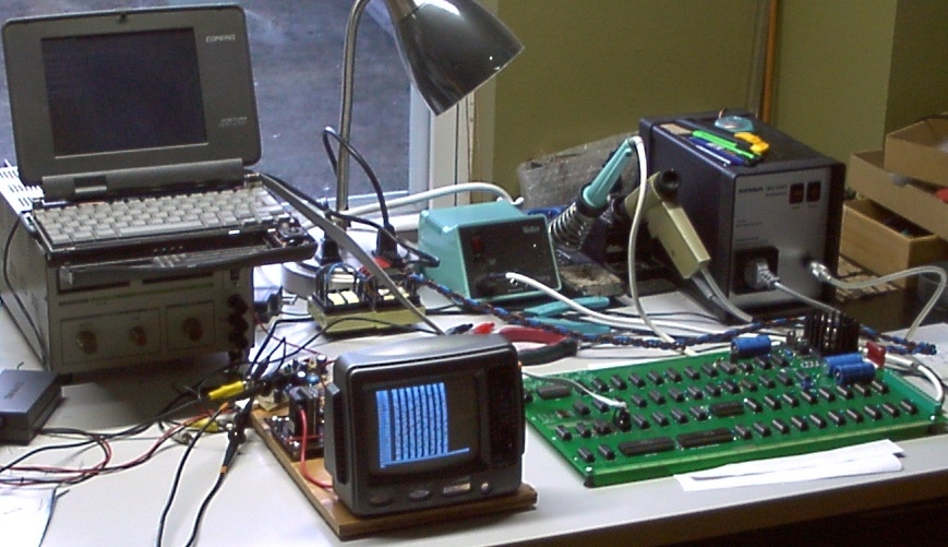
This glimpse in my lab shows the overall set up on my lab bench. You can see the "lab rat" and the Apple-1 clone making the video signal. The small notebook on the horizontal deflection power supply hosts the keyboard emulator featured here:
https://www.applefritter.com/content/apple-1-keyboard-emulator-cable-plans
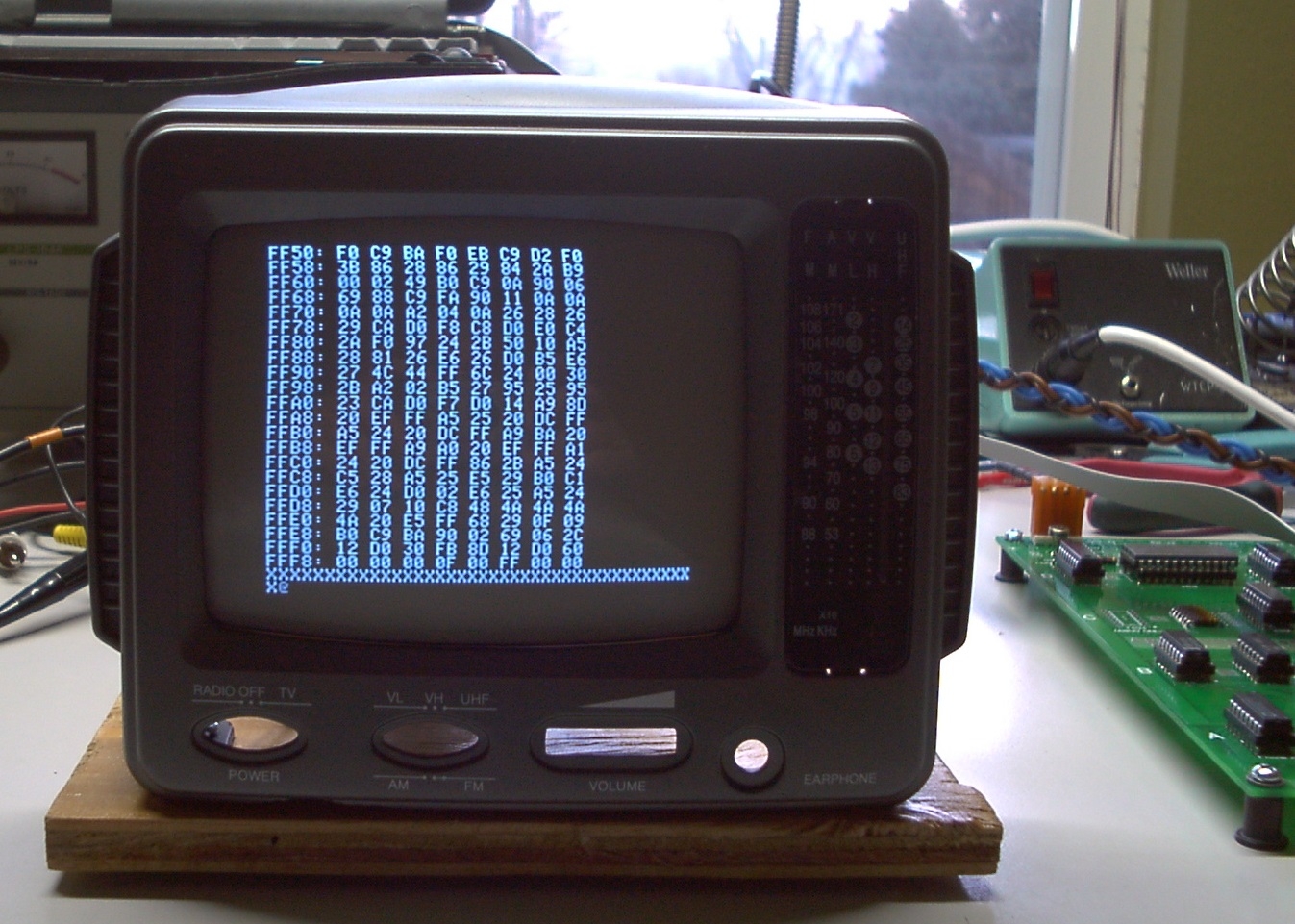
This is a close up of what is visible on the screen:
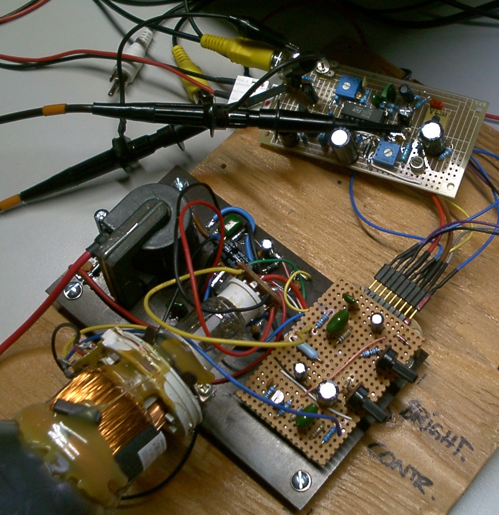
And this is the new electronics of the "lab rat":
Except for the picture tube, the deflection yoke, and flyback transformer, all the worthless and dubious "Chinesium" has been tossed into the trash can, where it belongs.
You may notice the resulting picture on the screen looks nice and crisp and centered, but my trained eye still can see some minor imperfections which need to be ironed out. I have also noticed some undesirable sensitivity of certain trim pots in the circuit: it's not easy to adjust them for a good picture. The dynamic range sucks. But with the "ATARI FLASHBACK" video game as a signal source, these problems are not seen and the adjustments are much, much easier and allow much wider margins to still produce a nice picture. This only proves that the nonstandard Apple-1 video signal is the culprit, and not my circuit design as such. I copied much of the circuit from the ST Microelectronics application notes and just recalculated a few components for the different vertical deflection coil. But ST does not give any hints about the video channel and cathode driver circuits itself (the TEA2037A IC is a horizontal and vertical deflection integrated circuit, and does not handle the Y = luminance channel). So I designed in the simplest Y channel circuit and retrace blanking circuits I knew and although they work fine with the ATARI FLASHBACK, they ain't great when they have to handle the "video signal from hell" (from the Apple-1).
So more work is required. Higher performance black level clamping and luminance (Y channel) circuits are required. But all the timing issues as such have been resolved. No "video fix" needed anymore.
Comments invited ! (Tell me if you would want to build one).


Hello Uncle Bernie!
I'm sure you have already noticed, but from the picture you posted of the raster there appears to be a geometry problem still left (besides the luminance issue). It is always hard to do adjustments on CRTs because so many components interact, and I cannot tell whether it is related to the horizontal drive, DC restorer or even the yoke just from one picture. Even harder when you are trying to build the electronics from scratch based on data sheets!
The project is interesting nonetheless and surely the solution is not far off. But forgive me if I cannot quite visualize how this 5" (?) screen could fit inside an attache case: more like the Otrona Attaché maybe?
In post #2, Robespierre wrote:
"... from the picture you posted of the raster there appears to be a geometry problem still left"
Uncle Bernie answers:
Oh yes, I know. But the root cause still needs to be found. At the moment my money is on the "mess 'o wires" which the whole contraption is. Could also be some kickback from the DC restorer / black level clamping circuit into the sync channel - despite I kept those separate. And if you would see how wildly the deflection coils are wound, yet another possible problem. I think those Chinese don't have machines to wind these coils, they probably do all of that by hand, terrible.
I'm quite fond of TV circuits because a quarter of a century ago I was the head of a design team which designed the very last generation of ICs for CRT based TV chassis. My small team did the analog / mixed signal parts. The digital team was much, much larger. All the actual signal processing was already fully digitized despite at the pins of these ICs the signals still were analog (except for the I2C bus). So each of these ICs had an ADC front end, a DAC back end, and a PLL to make the internal clocks. That was the last development stage for video / TV before everything was fully digitized throughout, from the tuner to the LCD panel drivers, with all analog video signals gone. About 20 years ago the Chinese then started to make these little CRT based TVs, essentially cheap throwaway gadgets meant as a gift to bring to hospitalized people etc. or anyone who could not access a real TV or a real radio set. The upside is that the typical specimen did not see much use so the CRT still has the full life in it (whatever that was).
About that CRT: the screen diagonal is 5.5" and the height of the picture tube is only 3.82" so I think it can be made to fit into a 5" attache case. The idea is that the "naked" CRT would sit at the bottom of the case when the lid is closed and pops up when the lid is opened. This requires some mechanics. But other than the tedium to make these mechanical parts, it's not a difficult concept.
I'm currently repairing an 8-bit Atari 600XL so I can use its BASIC as a test picture generator. This could allow me to get to the bottom of the slight distortions still visible. Alas, a quarter century ago, I was not able to take possession of the test picture generator we had in the TV lab, when the whole department was dissolved after all the work was done and the IC production had been ramped up. Another guy snatched it away. But I got the Tektronix vectorscope. Alas, useless for B&W work and probably useless now even for color TV work ... it's all a thing of the past. The analog TV / video era is over.
So far the current state of the work.
I'm curious about the interest (or lack thereof) from other Apple-1 builders and about any concerns they might have. Would they be too scared to handle a naked high vacuum picture tube ? Would they be afraid of the high voltages in the electronics ?
If these possible fears could be addressed and mitigated, it sure would be a nice little project leading to a parts kit.
Comments invited !
- Uncle Bernie
I doubt that I represent the concerns of Apple I builders (I have not yet built one), but to me the EHT of a picture tube is not really a concern compared to the exposed mains power circuitry of many Apple I builds I have seen. I would take precautions to use sufficient Glyptol isolating paste on the anode cup and dress the anode cable in such a way that it could never become kinked or pinched by any mechanical parts. There were special nylon clips made with a circular spacer ring to isolate the cable.
Hi there !
Just in case anyone out there is still interested in the "Sweet Little Monitor" project, here is a status update:
The cathode driver was optimized so now the picture is very sharp (better than the photos I could take).
There is still some crosstalk modulating the beam which manifests as a darker line (red arrow):
PDRM2370.JPG
And there are linearity errors in the horizontal direction:
PDRM2368.JPG
which, alas, are not easy to solve. Normally, TV circuits have a so-called "inductive reactor" in the horizontal deflection circuit which is a coil with a specially tailored core that is pre-biased with a permanent magnet. When the total magnetic field in this "reactor" increases, the core starts to saturate and the inductance drops, which has the effect to change the horizontal deflection such that it is more linear. Last generation CRT TV chassis had a chip set which would allow fully programmable correction of all relevant on screen distortions. But this super cheap little B&W TV which was the parts donor had no correction in the horizontal deflection circuit whatsoever. It is not feasable for me to build a suitable "inductive reactor" coil as I have no access to the exotic core materials needed for that. So I need to figure out an electronic means to do the correction ... not tough but time consuming. Somewhere in the guts of the USPTO there should be a cheap trick circuit that once was patented. Still working on finding that. Maybe some reader has a hint.
Another issue I saw was poorly stabilized overall screen brightness. When there is less "white" on the screen this "white" is brighter than if there is more "white" on the screen. So on case of the Apple-1, if you clear the screen and then do a hex dump of some memory region, the characters are nicely bright at the beginning, and the more characters are written, the darker the picture gets. According to my measurements it's the anode voltage which drops. So the flyback transformer was made as weak and cheap as it gets. Again, I need to find a circuit to compensate for that. I have one grid on the CRT available but had no time yet to investigate if that could stabilize the brightness if driven by yet another trick circuit.
All these flaws are rooted in the super cheap little B&W TV which was the parts donor. I have found out more about their history. According to the youtube video in the link below, they are the very last CRT based TV that ever have been made in the known history of mankind. Somehow, after everybody else had given up and all the color CRT production had been shut down worldwide (thanks to flat screen technology) the Chinese still continued to produce small B&W CRTs well into the mid 2000's. And several Chinese TV manufacturers put these CRTs into the type of super cheap "gadget" TV/Radios we are using as parts donors. The overall style was the same and the circuitry also was almost the same, but there were subtle differences and so the picture quality ranged from horrible to bad. According to the youtube video, these little TV/Radio combos were attractively priced at $14.95 or so (blowout / last gasp sale ? --- I got one with an original sales receipt that was higher) so people bought them without much thinking and when they found out how bad the reception was (and how few analog TV stations were left in the USA) they packed them back into their box for a long sleep in an attic or basement or storage unit. This is our chance ! Because according to this (non) usage pattern, the CRT is practically as good (or bad) as new. And the video also claims you can buy these at thrift stores for a few dollars. I regard this as a great opportunity. If the quirks caused by the basic salvaged parts set (CRT, deflection yoke, and flyback transformer) can be electronically compensated for, to get a good enough picture quality.
Here is the link to the youtube video telling the story of these little B&W TVs (12.5 minutes long):
https://www.youtube.com/watch?v=-Dlk9G2ADjs
Comments invited !
...and here you are doing tube exact same thing as myself...
although I have a 5" Amber CRT I got NOS a little while back...
I still have to squeeze everything down in size a bit to fit yet tho.