Finally recieved a real W65C02S from Mouser today and it is in the IIe with the adapter board working like a charm. I will run drive tests later tonight but having spoke with Bernardo at the Byte Attic and hearing he had no issues I am predicting all will be well. Now that I am confident the design I will put the board files up on pcbway for everyone.
Anonymous
User login
Please support the defense of Ukraine.
Direct or via Unclutter App
Active forum topics
Recent content
Navigation
No Ads.
No Trackers.
No Social Media.
All Content Locally Hosted.
Built on Free Software.
We have complied with zero government requests for information.
I'm curious as to why one would need an adapter board. Isn't the 65C02s pin-compatible with the 65C02 and 6502? I would've figured (perhaps naively) that you could just plop one right on in.
Is there some extra circuitry required to get the Apple II to handle the static core or something like that?
Unfortunately they are not pin compatible. This circuit has a cap and an a couple of pull up resistors based on Byte Attics circuit here...
https://youtu.be/BtxW8AWfh9s
The W65C02S has different pinouts to the original two, 6502 and 65C02.
W65C02S PinOut.jpg
6502-65C02.jpg
For those wondering, the differences with historic 6502s, and the remedies are listed here in Western Design Centre's website:
https://www.westerndesigncenter.com/wdc/AN-002_W65C02S_Replacements.php
Just curious why you had to change to a modern 6502.
Is it because of a dearth of replacements?
Don't get me wrong, I'll line up for one of those PCBs as I have some WDC65C02S chips in the drawer for emergencies.
Yes it was because of the eventual decline in availability of the originals and the fact that the W65C02S is still being made. And the number one reason was that it was FUN To do LOL.
I find this very interesting and I also wonder, is your adapter exactly like "The Byte Attic" (only that is a nicer design with PCB)?
I wonder if this is a generic solution of a W65C02S to 6502 adapter and not only aimed at the Apple //e but all 6502 based hardware (computers, arcade games etc.)? For example, in the arcade world defective processors isn't anything unusual and it would be really nice to be able to use this kind of solution there as well.
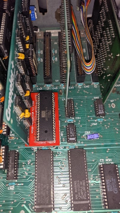
Yes it is, see the back.
PXL_20220216_171139137_1.jpg
Nice! :-)
Not to take away credits in any way, but, the credits on the PCB, can they be moved? Thinking that the PCB and solution would benefit from being as small as possible to fit all types of hardware it would be used in (other big chips sitting close to it etc.). Obviously if possible and if there isn't any use for the space. Maybe the text can be moved "inside" the socket?
As with my Disk Sleeves I did this for fun and to learn a new piece of software, all files will be available when I get around to putting them up on pcbway. The cut lines can be moved easily as well as the text. As it is cards fit over it in the slot. I am making a version with the surface mount version of the chip that is more compact but it may be a while before I can have it produced and test it.
I understand, I'm grateful for your contribution for sure!
As I have never edited this type of files, do you recommend any software (Windows) to edit such a file/project?
Thanks!
In his video the Byte Attic dude discovered that the Apple does not like intervening logic between the W65C02S and the socket. He poosulated that the timing of hte bus signals are on the edge of tolerance (probably true) and even the 8 ns delay by inserting a buffering chip between the CPU and the socket on the motherboard caused enough timing delay that the CPU could not read from ROM properly and start the machine up.
I honestly don't know why he felt the need to boost the TTL signals to CMOS 5V levels into the W65C02S. Western design centre's application guide clearly states that the chip will work (with the required pin modifications) quite happily in the Apple II.
His application of the adapter board (with intervening voltage boosting logic) was for VIC-20 use but I have a feeling that the VIC (and other vintage machines like the Atari and arcade cabinets would work fine without that logic.
Drive tests in Apple IIe Diagnostic V2.1. MECC as well as a couple of disk image writes with ADT. No read write issues for those worried about the timing with the new chip.
https://www.pcbway.com/project/shareproject/Apple_IIe_CPU_Adapter_W65C02D_014cc82b.html
Thanks a lot for sharing this! :-)
I have 6 blanks available, one per person, only cost is that you cover shipping. PM me if you want one. Please don't reply in thread.
board top.png
Board Back.png
Board.png
Very cool! :-)
ordered.png
Similar design but not exactly the same; W65C02S w/ adaptor for drop-in replacement of 6502 in Vic-20, Acorn Electron | eBay
I looked at those a little while back and thought about grabbing one and then I'd have an excuse to buy an old VIC, and then yet another rabbit hole that would lead to divorce ROFL
An updates on the surface mount version; Canada Post changed from deliver today to delivery Thursday on the tracker. I have the chip, caps and resistors patiently waiting.
Now for the design. All circuit credit still goes to Byte Attic (check out his Cerberus project really cool). People have asked about the reason for some of the components, the resistors in particular. In BA's original design video he stated the second resistor wasn't really needed but didn't hurt, fine consession on that. However the first is actually recommended on WDC does state the following "Add a 3.3k Ohm pull-up resistor on RDY (Pin 2) if not being driven; Add a 3.3k Ohm series current limiting resistor to RDY (Pin2) if being Driven.". In addition to disconnecting Pin 1, and tying BE to VD.
Cheers!
IMG_20220413_181601.jpg
Wow, that looks great! And low profile, to boot.
Will see how one looks after my attempt at smd soldering goes LOL
I use SMD solder paste dispensed from a syringe and a hot air rework gun to do SMD stuff like that.
Ya, my hot air station gave up the ghost when I was working on some PS4's a couple years ago, haven't replaced it yet. It's my Birthday next month, ;) .
In the mean time i may try my fine tip skills just so I can see how well my blood pressure meds are working.
Doing a SMD soldering job on a chip with SSOP pin spacing with a fine tip iron is a special form of self-torture.
drag soldering. works great for me.
Likely the best option in this case. Use plenty of rosin (like the stuff used in many of Joe Strosnider's Apple II repair videos) and a good clean beveled tip.
Low temperature rosin core solder (0.05 dia. or so) and 300 degree tip temperature should do the job quite nicely. Sweep outward from the leads after applying the solder to break up any bridges. Cool the chip between solder application to each side to protect the IC. :-D
Recieved my boards from JLCPCB, soldered up 1 and tested it on my //c, looks nice, very low profile.
This is meant to replace the 65C02 on my //e PAL, will make another to enhance my //e NTSC.
Will test it on my II+ clone as well. Is there any benefits in doing that? is there an enhanced II+??All credits goes to the saint and byte attic, without them I don't even know about the WDC65C02S.
282053601_10227523857431380_497031348179361556_n.jpg
282302660_10227523857951393_8213018913266869697_n.jpg
Run loop tst over last few nights with no erros.
Total 2 boards made - easy to handsolder.
Tested on.
Apple //e PALApple //e NTSC
Apple //c
RX8800 (Apple II+ clone) - needs pull-up resistors.
Did the SMD version ever get posted anywhere? Can't find it.
I built several of the DIP version. I never saw Gerbers for the SMD version. The DIP version works fine, but creates a challenge to long cards in the slot it is in front of. I'm not a fan of soldering SMD, but this one looks easier than a lot of them and it would have the advantage of being basically as low profile as a DIP part so there would be no clearance problems.