I finally build up the courage to start my build, having acquired all of the parts, watched way too many videos, and read / reread all of the available guides.
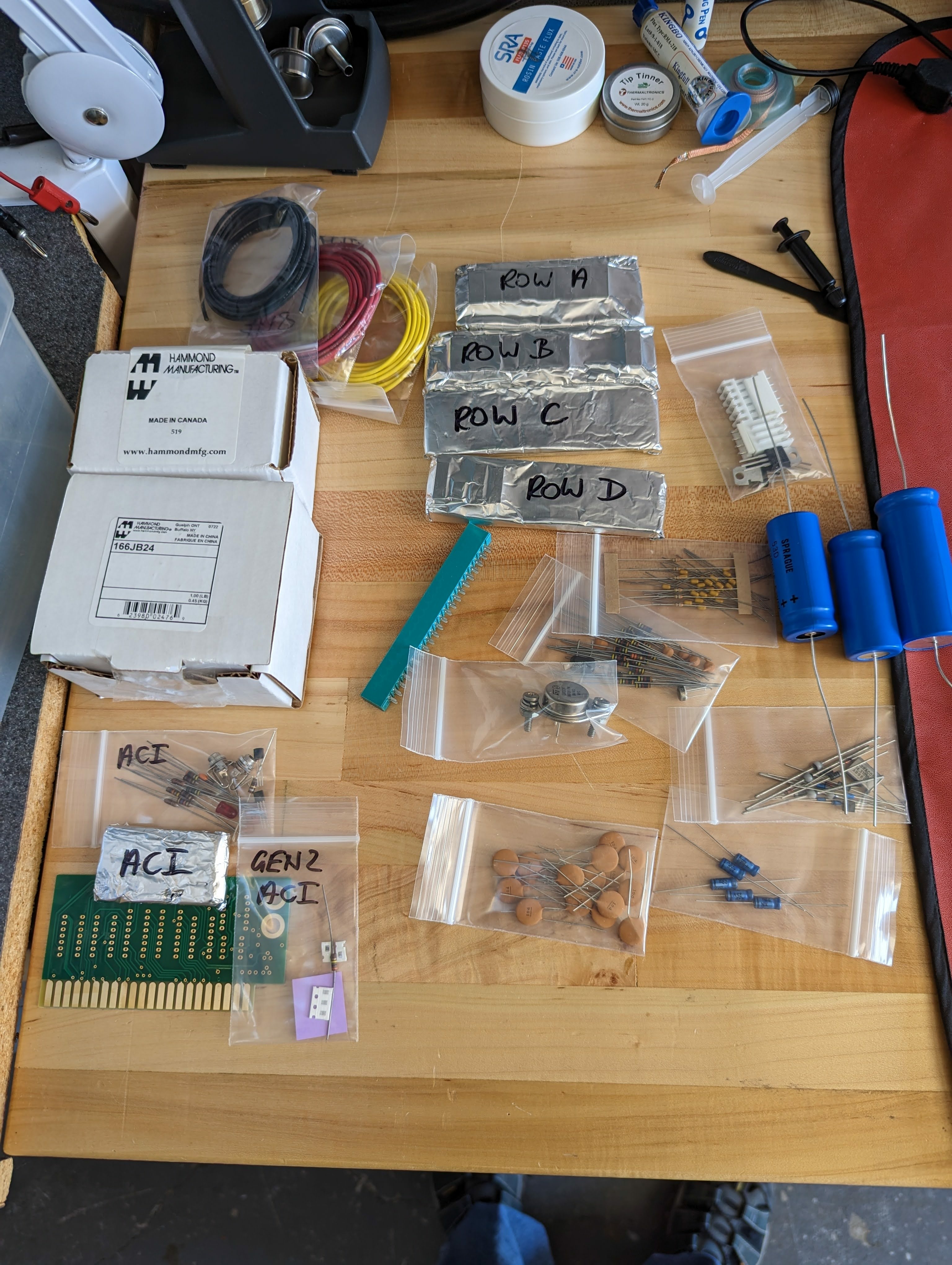
My build is using:
- Uncle Bernie's parts kit, and his ACI gen2.
- Newton PCB
- Newton keyboard
- P-lab jukebox
- Misc parts from digikey.com, anchor electronics, eBay, etc.
- Super high quality copies of the original manuals (incredible! )
- Eventually some kind of case and or display mounting. TBD
A huge thanks to this forum and all of the enthusiasts here and above who made this possible.
I'm going slow because the build (for me) is a ton of fun. I build as many retro kits as I can get my hands on since I'm an old heathkit fan.
I'll post my progress as I go, just a few components soldered down now. I test everything as I go, which usually improves my success rate.
You have very cool kit, good luck building it!
Good luck with your build!
Keep us posted! :-)
Best,
Claudio - P-LAB
I made a couple of stupid mistakes soldering, despite being super careful.
Thankfully I have a vacuum desoldering tool. It made quick work of the repairs without damage to the board. I am no expert, and having good tools feels like cheating!
PXL_20230129_233707663.MP_.jpg
Next step, check out the power rails and do some cleaning.
PXL_20230204_233019109.MP_.jpg
Power supply built (at least temporarily), power cable built, and all rails are good!
PXL_20230205_224745775.MP_.jpg
PXL_20230205_221357532.MP_.jpg
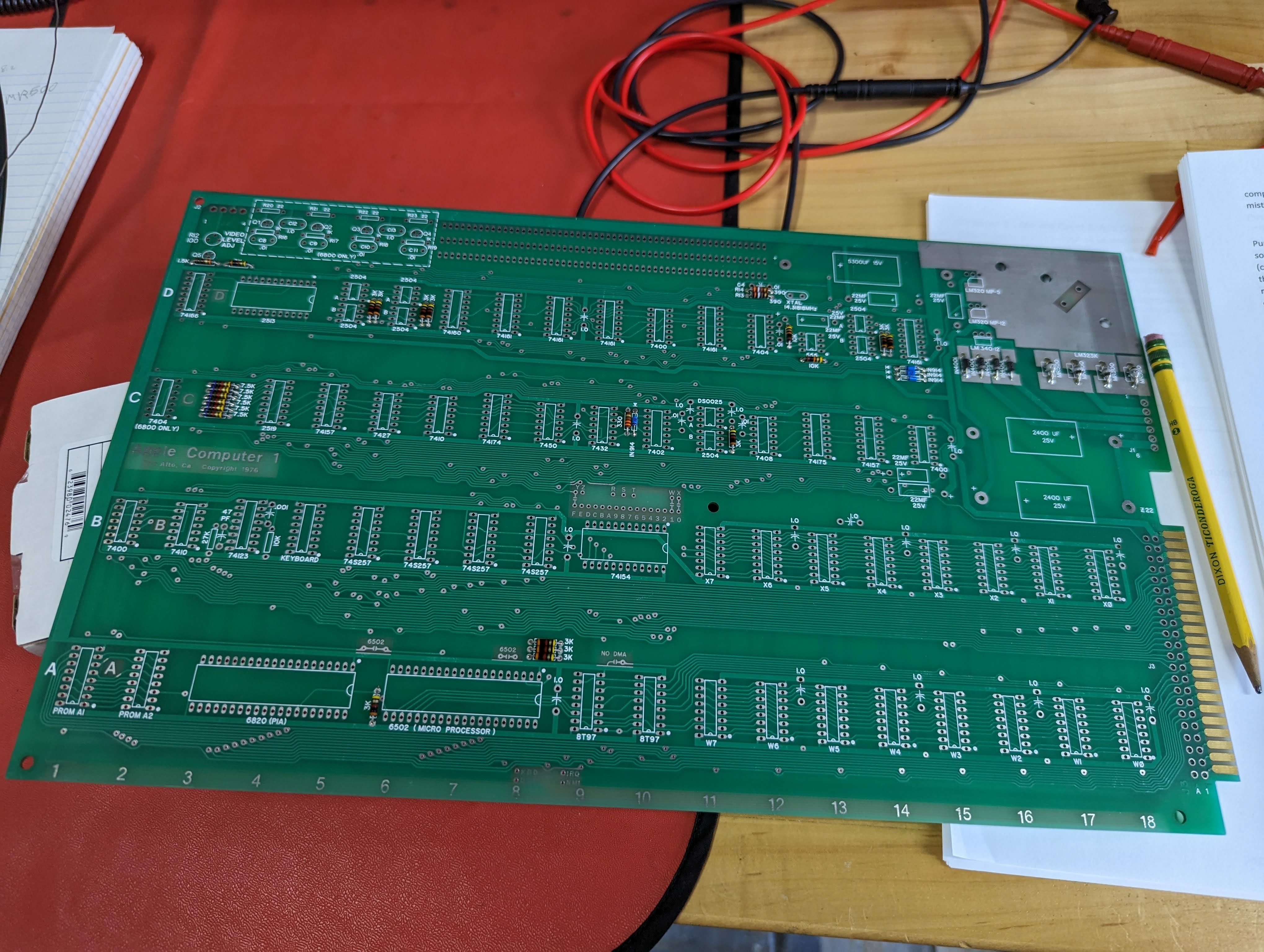
All built... sort of... I skipped a step or two in hopes I'd get lucky. In fact, a whole lot is working great and I'm super pleased. It boots, runs the ram test in prom, keyboard works (and looks great).
Unfortunately, I get bit errors and the video is all twitchy (no surprise I'm sure). I tried two panel TVs, and one doesn't work at all. Sadly I don't have a crt. So, I probably need to build Uncle Bernie's video fix.
In the meantime I will debug the ram errors, but first I'll do the reliability mods (as I should have in the first place!). P-labs sd card storage has a ram bank replacement capability which I can play with. I also have a retro chip tester. So, lots of things for me to do and try.
PXL_20230212_013306292.MP_.jpg
PXL_20230211_233211646.MP_.jpg
PXL_20230211_234213331.MP_.jpg
Uncle Bernie's reliability mods fully installed. My dram errors didn't go away until I installed the 390 ohm pull-ups on the dram address lines. Unfortunately my video is still not displaying properly on my lcd panel, but I mostly expected that. I have parts on order to implement Uncle Bernie's video fix, so making good progress!
PXL_20230218_230255048.MP_.jpg
PXL_20230219_024639993_exported_700_1676775896552.jpg
Added Uncle Bernie's video fix and I now have a usable and stable picture. I'm playing with some of the component values to see what gives me the best picture on my two monitors.
image.jpg
Before finishing up the video fix, I thought I should get the clock frequency more on target. Once I replaced c4 (10 nF) with 12 pF, my dot clock is much closer (see my post on the crystal thread).
I then finished installing Uncle Bernie's video fixes, and am very pleased with the results (see the other thread). This was some tricky/challenging soldering for me!
PXL_20230304_234949114.MP_.jpg
While I was at it, I checked the pulse widths out of the 74123, and they look fine. I was a little mislead by the 480ns pulse as I initially was looking at the negative cycle. Looking at the schematic, it seems the positive pulse is used? Fortunately, it is within 5%. It is odd how the duty cycle is nearly 50%.
image.jpg
image.jpg
Next up is probably an extended burn in / stability test / cleaning.
After running the memory tests for a while, I got impatient and wanted to play. I plugged in P-lab's microSD storage card and started to mess around. I know I need to build my ACI, but I couldn't wait. The storage card made it super easy to load all kinds of programs. Of course I had to run the apple demo ascii art to show it off!
PXL_20230306_005916724.MP_.jpg
Next step in my build is to make a case. However, as I debated different designs I just couldn't bring myself to hiding this piece of history in some box. Yes, a case would be convenient and would help protect it, but I wasn't happy with the idea.
I thought about the acrylic cases, and they strongly appealled to me. However, I couldn't find one that fit the Newton pcb, and I wasn't confident in my plastic workmanship skills. I didn't want to end up with something ugly.
So, I got the idea of mounting the pcb to a decorative piece of wood that would be both a stand when in use and also a nice wall hanger. This also solves my storage problem as my apple 1 will always be within easy reach (unlike my many other projects) when not in "use".
As usual, I went a bit overboard. However, I'm quite pleased with the results. Cost wise, this was super cheap to make.. Yet,, I think it is worthy mount and display.
I started with a plank of Spalted Maple. I had to settle for this as I couldn't find any Koa that I liked. It was a simple job to sand it flat, then I finished it with four coats of water based urethane. I carefully sanded between coats to get a nice shine. I think the light Maple contrasts nicely with the green pcb without overwhelming it.
I put feet on the back so it works well as a stand. The pcb is mounted with some nylon hex offsets and stainless m3 bolts. I ordered a plaque from ebay to finish it off.
image.jpg
PXL_20230422_160915567.MP_.jpg
PXL_20230428_223604822.MP_.jpg
PXL_20230429_005932998.MP_.jpg
PXL_20230429_005837564.MP_.jpg
PXL_20230429_005818755.MP_.jpg
PXL_20230428_224314384.MP_.jpg
That looks real good. Nice work!
I like the wood / circuit board combo. It looks solid :-)
I just finished my build, and I wanted to just say thanks for all the high res pictures of your process. They saved me a lot of time with my own build.
I am happy to report that my Gen 2 ACI works flawlessly. The instructions were easy to follow, and having all tested parts made it a breeze. Thank you again Uncle Bernie.
I believe my ACI might have been an early gen 2 version, but so this might not be all that useful. Here is a closeup of the surface mounted parts anyway:
PXL_20240324_231859713.MP_.jpg
PXL_20240324_231859713.MP~2.jpg
And the final product:
PXL_20240330_204020771.MP_.jpg
I tested it with an old TRS-80 cassette recorder and I was able to save / load a block of memory without any issues. The ACI LED seemed to light normally. As an added bonus, I now know my cassette recorder works too!
BTW: I ended up melting/shorting the mono 1/8" phono jacks that came with my kit. I got a little careless with my soldering -- oops. Being impatient, I just permanently attached two mono cables that I cut out of a single stereo cable. I don't expect to be using my ACI all that often, and this also saves me the trouble of having to hunt around for appropriate cables (and it cost me nothing to fix it).
P.S. Why did I end up melting the jacks? The jacks kept coming loose when I plugged in the cable (annoying). Also, I wasn't that happy with how the jacks could potentially short together if they started moving around. I got the bright idea to solder the jacks (just the locknut, actually) in place. This definitely kept the jacks from moving side to side, but still allowed them to become unscrewed. Worse yet, in the process I must have melted the insulation between the layers of the jack, and one became shorted to ground. Fortunately, I was testing things as I went, so didn't short out anything while it was live. Perhaps others have done this more successfully? Anyway, if the captive cables bother me in the future, I can always replace them with proper (authentic) jacks.
In post #16, 'mrthreeplates' wrote:
" The jacks kept coming loose when I plugged in the cable (annoying). Also, I wasn't that happy with how the jacks could potentially short together if they started moving around. I got the bright idea to solder the jacks (just the locknut, actually) in place. This definitely kept the jacks from moving side to side, but still allowed them to become unscrewed. Worse yet, in the process I must have melted the insulation between the layers of the jack, and one became shorted to ground. Fortunately, I was testing things as I went, so didn't short out anything while it was live. Perhaps others have done this more successfully ?"
Uncle Bernie comments:
This is a known problem which, alas, can't be avoided, as the only source left for the authentic looking jacks is China, and they are very poor quality. Back in the day they were "Made in Japan" and the riveting was done correctly. The Chinese who acquired the tooling from the Japanese probably did not get all the know-how with it, or the tools are worn out, or the material (the alloy) is wrong. So their riveting cracks and is loose. This can only be fixed by soldering the cracks and adding another wire to prevent rotation of the otherwise unconnected tab. I also solder the base of the jack to the PCB. Here is an example:
PDRM4055.JPG
This is an older photo in which you can see the solder joints at the base of the jacks which prevent rotation of the jack, and the extra wire which prevents rotation of the otherwise unconnected tab. You can also see the cracked riveting. Which in this case was not fixed. It can be done, though:
Fixed_Jack.JPG
Caution and soldering skill is necessary not to fry the jack. Melting the plastic spacers in it causes shorts. This work should be done before the jack is installed in the PCB. Not that it is not necessary to solder the cracked rivet all around. Just a few solder joints are enough to stabilize it.
One of the "tricks" is to use a 60W strong, temperature regulated soldering iron with a "screwdriver" tip. Such as the old Weller WTCP-S. This tool with the proper tip can bring enough heat to the solder point in only 3-4 seconds and this does not give the plastic enough time to melt away. Any attempt to do this with a weaker soldering iron or a finer tip must fail because you can't get enough heat to the solder joint withing that 3-4 seconds time window. Soldering irons without temperature regulation can't do this either, they are too hot.
I wrote instructions on how to build a Gen2 improved ACI card which cover the latest version of the PCB (now sold by Ebay seller newton-computer, as my work was based on his Gerbers).
You have an earlier Gen2 inproved ACI card with the Zener diode. This was necessary as the LM4040 was sold out during the supply chain disruptions caused by the pandemic. So I used Zeners which I had to hand select for a tighter Zener voltage. Once the LM4040 became available again, I switched to it because this saved me the time to hand select the Zeners (a better deal despite the LM4040 costs 10 x of a Zener). But as the PCB was optimized for the Zener, the LM4040 has to be soldered in slanted. This was corrected with the last revision of the PCB, see here:
SMD_Step3.jpg
Performance wise (readback reliability) all Gen2 improved ACIs are the same, so don't whine if you have an earlier version. I tested all versions (Zener, LM4040 shunt regulator, and series regulator) on a test bench where disturbances were injected into the supply rails using a function generator. All versions of the bias circuit showed the same robustness. The new impedance balanced input circuit combined with well matched resistors does the trick, not the bias circuit. I have hunch that it my be possible to replace it with just two low ohmic resistors of the same value forming a divider of the supply voltage to get 2.5V. But I never tried that.
Just for those having Gen1 improved ACI, these also work OK when you use a digital audio source. You could put the Gen2 input circuit in using discrete leaded components. But only SMDs can 'hide' below the IC sockets, so the "authentic looks" are preserved. But it is known that back in the day, many Apple-1 owners attempted to modify the ACI to make its readback work better (they failed, because even Woz coudn't fix it). If my hunch mentioned above is right, you would need to add only two resistors and two axial 100nF capacitors to a Gen1 inproved ACI to turn it into a Gen2. Maybe somebody works out a plan to do this, based ont the Gen2 schematic.
I will soon publish the whole ACI document here on Applefritter, and it also contains the full schematic and the listing for the 'extended formatting page'. But I was struggling with getting that listing properly formatted which is rooted in some quirks of the assembler I use and then on my lack of proper typesetting tools which could import pdfs of the listing into a regular Open Office document. Open Office is free software but it ain't the Adobe Desktop Publishing suite which I won't buy to just be able to make that one document looking nice. So you will have to be patient until I sort out these difficulties.
- Uncle Bernie
@Mrthreeplates
Gorgeous replica build.
Nice job!
Best,
Logan
Great build, and I like the wood! I tend to use Osmo oil finish. My 1984 VME system is in an oak cage, since I threw the cheap metal cage out.
Could not help noticing the pdp11/70 a few posts back