
Hi all, I am having some issues with my Unitron 80 column card (Videx clone). The machine was sat for 30+ years so I have no idea whether it had any pre-existing issues, but lets assume not!
When I enter PR#3 the blinking cursor on the 40 column display disappears (as expected), however when I then switch monitor inputs to the 80 column card, there is nothing displayed. Ctrl + bell results in silence, any pressing of keys followed by return results in silence, however I can press reset to be returned to the 40 column output. When I switch to 80 column I can also hear a change in the pitch of the electronic hum.
I have removed all of the chips, cleaned the sockets, re-inserted them, and cleaned the contact on the card and the slot, as well as checking continuity on the cable.
The cable is homemade and a bit janky, but it appears to be wired correctly.
The chips I have easily available to buy are:
The CD4013BE, 74LS02, 74LS139 (does it matter if this is an N or AN?), 74LS00, 74LS157, 74LS132, 74LS86 (does it matter if this is an N or AN?), 74LS166, UPD4016C-2, and the main controller chip, the HD46505 SP-1.
I can record the behaviour if you think it would be helpful!
I do also have intermittent issues with my Disk II card, so is there a chip on the motherboard which relates specifically to handling expansion cards? Perhaps that could be the issue if so?
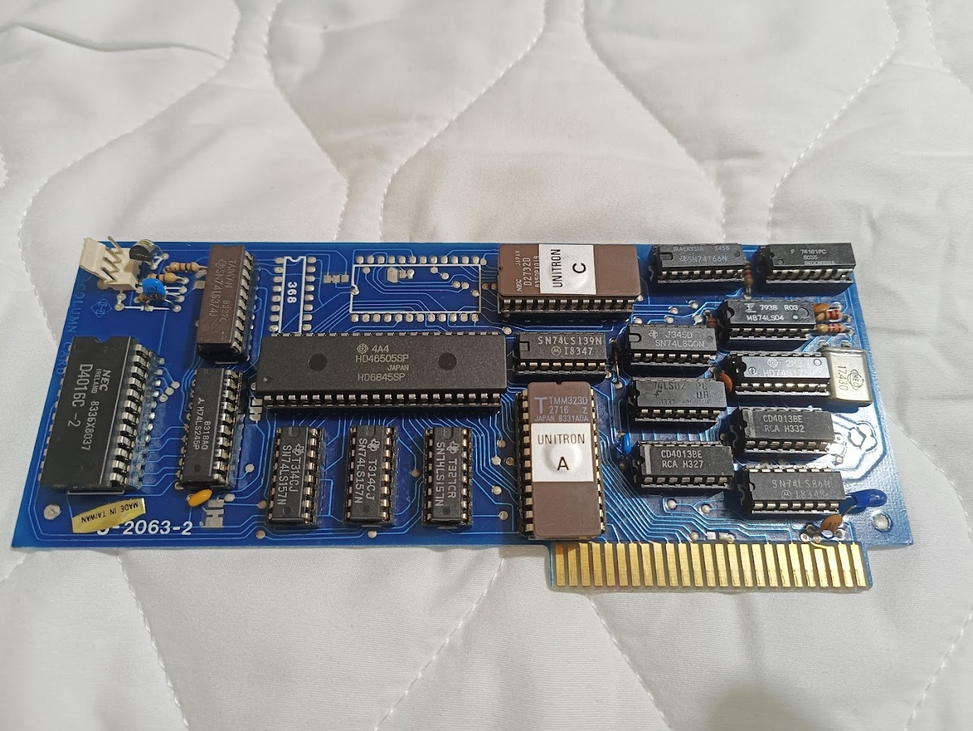
Images of the card:
Any advice appreciated!
It's possible the EPROM has gone bad. Can you do a C300L from the monitor and post the results.
This is a good suggestion, although usually if the EPROM on a card goes bad PR#3 will dump to monitor... But it is possible it is just freezing up. But most of the time bad EPROMs are 00 and FF, and those will usually crash it.
Another possibility I just thought of that could account for a blank screen... if the character EPROM (which I think is the 2732) goes bad and is all 00's... that would produce a blank screen... But that would not account for the lack of "beep", so provably unlikley to be what is happening here, now that I think about it further.
I'm sure I can do that.
Unfortunately I don't really know what I'm doing yet... 90's computers are more my familiarity, the Apple ][ is a new aquisition I'm trying to get fully working!
Could you talk me through it? How do I open machine language monitor first of all? And how do I "do a C300L"? Do I just type C300L? :)
Also I should note that my machine is a ][ Europlus, which is essentially just a Plus, but it uses PAL not NTSC. I'm not sure if that would have any bearing on any of the troubleshooting, but I thought it would be best to mention!
The first thing to check is to see if there is a clock signal on pin 21 of the HD46505, because a black picture if exactly what you get when the oscillator is gone and there is no clock signal. These large can crystals are prone to breaking if dropped.
Would that also result in no beep / etc though?
I thought that if the controller (assuming thats what it is) had failed, then I would have no video, but ctrl + bell should still work.
Akagi wrote:
I am not sure, but you can simulate a dead oscillator by simply removing the 74LS04 chip from its socket and seeing how it behaves without it. If it's exactly the same as right now, it's a good indication that it's the oscillator.
Great idea thanks!
I took out the 74LS04 and it behaves exactly the same. :)
So would that point to this guy here?
image_2023-05-11_142619949.png
Is there a way to verify this with a multimeter? If I probe the legs of the oscillator?
Yes, it's either this crystal, the 74LS04 itself or the 74LS161. You can't do much with a multimeter - the frequency is 17.430 MHz. You need to connect an oscilloscope or a frequency counter to pin 10 of the 74LS04 or pin 21 of the HD46505.
Here are the schematics: https://www.applefritter.com/files/2023/05/11/Videx%20VideoTerm%20Schematics.pdf
There is a whole bunch of 74LS161 chips on the Apple II motherboard and one 74LS04 in position C11. You can try swapping.
Thanks. I swapped the 74LS04's, no change.
I don't see a 74LS161 on the card, but there is a 74161PC
Is that the same?
Yep, same one.
No change with that one swapped over either.
So everything points to that little oscillator? I've asked my electronics guy if he has one of those in stock, and I guess we'll see.
Thanks for all the help!
It's either that or the ROM is non-responsive.
When you invoke PR#3 it calls the ROM on board the card. If it can't access it, nothing really happens.
You should really test the output of that crystal before blindly replacing it.
In fact, someone earlier suggested seeing if you could read the ROM on board the card.
You can do so from the monitor prompt.
Enter the machine language monitor from the Applesoft BASIC prompt "]" by typing CALL-151
You'll get the "*" prompt for the machine language monitor.
type C300L <return>
and you should get something similar to the following:
c300l.png
If it does not read the ROM then the first line would probably start with C300 - FF
This is what I get from that.
IMG20230511181706.jpg
I don't really have a way to test the output, my multimeter doesn't have a frequency setting, and I don't have an oscilloscope... I know a man who does though.
Looks like proper executable code, so I doubt the EPROM is bad.
Yep, the firmware PROM is good. My Videx clone reads exactly the same thing:
Firmware.JPG
Now you can use this approach to test the font PROM too. Simply remove "Unitron A" and put "Unitron C" in its socket. You should get this:
Font.JPG
Crystals are very sensitive to capacitative and inductive loading in their circuit, so they can't be probed directly without using an active FET probe ($$$). But if you tried swapping the inverter chip that drives the crystal with a known working chip, and the clock output is still not present, it points either to the crystal itself, compensating capacitors in the crystal circuit, or the board traces or solder joints.
Luca
Looks good. :)
Thanks, that sounds promising. I do seem to be able to get the correct one though so thats good. :)
The exact frequency of the crystal is not so critical, but it's good to be close to the original, since it is the pixel sampling frequency. The higher the pixel sampling frequency, the more pixels you can fit on the screen, so in essence it determines the width of the picture. My Videx clone card came with 16 MHz crystal and the picture looks like this:
Crystal16MHz.JPG
When I first got it though I was experimenting with different crystals. Here is how it looked with a 14.745 MHz crystal:
Crystal14.745MHz.JPG
Monochrome CRT monitors are very forgiving, but once you veer too far from the original frequency, the monitor might start having trouble with the horizontal sync, since your lines are no longer exactly 64 microseconds, which is what the card is set up to compensate for. Here is what happened with 17.734 MHz crystal:
Crystal17.734MHz.JPG
Good to know, thanks. I'll see if I can get, say, a 17MHz. The images are very helpful! Its fun to experiment like that.
I've ordered a couple of 16.934MHz. It was that or 17.734MHz.
I would have gone for one of each, as the 17.734 MHz is a bit closer. If your card was tuned for 64 μS with a 17.430 MHz crystal, then you would get:
16.934 MHz --> 65.9 μS
17.734 MHz --> 62.9 μS
But I think your monitor will be able to handle a 2 μS deviation in either direction.
I guess at the very least it will display *something* if that is indeed the issue.
I'll be happy enough with that! Even if I have to change it again.
Yes, all of the posts about the crystal are fine. But it doesn't explain why you don't get a beep when active. You still have more troubleshooting to do before the board will work correctly....
I thought, based on other posts, that it was likely to be the whole issue.
I guess I will find out.
But if it is not, any further pointers will be greatly appreciated. I am perfectly happy replacing chips and small components, but I have no experience with vintage computer equipment, so I will need some handholding for the diagnosis "educated guesswork" we are doing. :)
You would not get a <Ctrl><G> beep in 80-column mode without a running oscillator on the card. The HD46505 is the one that generates that beep and without a clock signal it cannot do anything.
Interesting. How would it come out the Apple speaker then?
Maybe a good test would be this:
1. Type PR#3 <ret>
2. Type PR#0 <ret> (blindly)
3. Type IN#0 <ret>
If the firmware is all working, you should be back in 40 col mode and everything should be just like is was before step 1.
Actually I was wrong. I just removed the video processor of my Videx clone and I still get the slightly different pitched beep in 80-column mode. I have this card:
VidexClone.JPG
Still feels like a firmware issue. That's what generates the slightly different beep sound as well.
Maybe try this from the monitor:
C300 <ret>
C800L <ret>
Let's see if the IOSTRB space is working as well. Otherwise it might take a complete EPROM verify or re-programming from a known good source.
I went to go and try that and... I have a new problem, I now can't get the machine to boot at all. - Apple II not booting
Actually you can dump the entire 1K firmware into a file using the following command from the Basic prompt:
BSAVE FIRMWARE.BIN,A$C800,L$400
After that you can post if here for verification. Here is mine: C80CPL-3 Firmware.zip
Your Apple II might stop booting after adding and removing cards, because the motherboard flexes and some sockets have bad contacts. Just flex it a few times manually and it should start working again.
I'll try it.
I was actually worried I was doing damage pressing chips without removing the board because of the flex.
I don't like flexing board noises lol.
Okay that's sorted now, I had to reseat all the chips on the language card. Some of them were a little crunchy.
Then it fired up!
The language card is also a blue Unitron.
Since you seem to be missing the F8 ROM on your motherboard, it WILL NOT WORK without the Language Card installed. Until you get everything sorted out, I'd consider moving the F8 ROM from your LC to the motherboard. Then you can remove the LC. No need to move the RAM chip; the computer will work fine without it. It will just look like it has 32K of RAM. Then you can get back to diagnosing the 80-col card and any other intermittent issues you seem to have without worrying about any LC problems.
Don't use the firmware of my card for comparison - it's different. You can download the original Unitron firmware for your card from here: http://www.applelogic.org/UnitronAndI.html
I don't have a way to get files off of the II sadly.
IMG20230514214011.jpg
No need for that, the picture is sufficient to reveal several things:
A0is an unknown instruction "???", the next line saysA0is an "LDY" instruction, and the third line saysA0is a "BRK" instruction.) This inconsistency occurred because the ROM did not respond, so the processor was just reading whatever "vapor" happened to be on the bus.Under these conditions, the PR#3 command will cause the screen to freeze (no printing, no beep) because the PR#3 command sends all character output to the card, but the card's VIDOUT routine is missing because the $C800-$CBFF firmware is missing. Even if though the computer may "crash" into the monitor, any attempt to print a monitor prompt will cause it to crash again trying to call VIDOUT, which will cause it to crash trying to call VIDOUT...ad infinitum.
So IOSEL is activating the ROM, but IOSTRB is not. Let's search the schematic in Fig. 11 for components that might interfere with IOSTRB even when IOSEL is working properly:
This doesn't diagnose the cause yet, but it points in a helpful direction. If you've got a logic probe, hook it to pin 2 of the 4013 at U7: accessing $C300 should turn it on, and accessing $CFFF should turn it off. (Note that there are two 4013's on this card, so be sure to test the one in socket U7.)
EDIT: Unitron apparently didn't label U7, but in your photo U7 is the leftmost 4013 on the card...the one closest to the 2716 firmware EPROM. It's labeled "CD4013BE" and "RCA H327".
Thanks, that is extremely helpful!
So, the 7404 on the right (with the Fairchild logo, between all those resistors) I have already swapped with another 7404 from the motherboard, and there was no change in behaviour.
Unfortunately I don't have a logic probe. So I will have to go for the brutish approach of just replacing the 7402 and 4013 in turn, and seeing if there is any change.
I'll check to see if any of the expansion cards have those chips onboard that I can borrow, otherwise I'll order them in.
Looking at the diagram the 7404 is connected directly to the crystal, so if the 7404 could cause the issue, could the crystal also cause it?
The new crystals are arriving tomorrow, I may swap it over just to see. Unless you think that would be a waste of time. :)
That's funny, in Bulgaria we call this the bulgarian approach! :)
Speaking of which, you can still do quite a lot, since everything is fully socketed:
Green dot: you already checked it through swapping
Red dot: swap with the chip from the Apple II+ motherboard
Orange dot: swap with a chip from the Unitron language card
Blue dot: swap with the neighboring identical chip
Swap.png
It was the right most 4013!
I swapped all the others, no change.
Swapped those around, and I get display output but garbled, and it beeps and I can (semi blindly) execute code!
Ordering a replacement 4013 and we will see!
Its a shame we went through all this, and then the thing that hopefully diagnosed the cause was random chip swapping. But I suppose thats just how it goes sometimes! Replacement chip(s) ordered. Hopefully that will solve it... I will of course let you know. :)
Yes, but it didn't become obvious until post #41 above that the issue is in one of the logic chips.
I'm a little sad I don't need to replace the crystal, I bought a new soldering iron for that. Haha!
I guess I will need to find something else that needs repairing now...
Look up one of the projects people have posted on here that have a github repository... order some PCBs from JLCPCB or PCBWay and then order some parts and start soldering!!!
I decided to desolder and re-solder my video switch (a cheap modern thing from Amazon that I use to switch between 40 and 80 col) and in doing so, managed to snap off part of the video connector...
So then I had to bridge the traces from one of the audio connectors, and cut the traces to it, to use that as the new video connector.
I don't know if it works yet, because I accidentally broke the video cable for my monitor, and I can't find a replacement... Its all going well. Lol!
What kind of soldering iron/station do you use? I used to use a small Weller, but I upgraded a while back to a Yihua 939D+ which is a lot better.
Soldering takes a soft touch, using the right solder, the right temperature, etc. Practice makes perfect. If you are breaking things you are probably using too much pressure and maybe too much heat.
Pages