Hello,
I am new to this forum and I also apologise for my English, it is my second language.
Anyway, I started building my Apple I replica about half a year ago. However, after I finished the terminal, I discovered that it wasn't working (sort of).
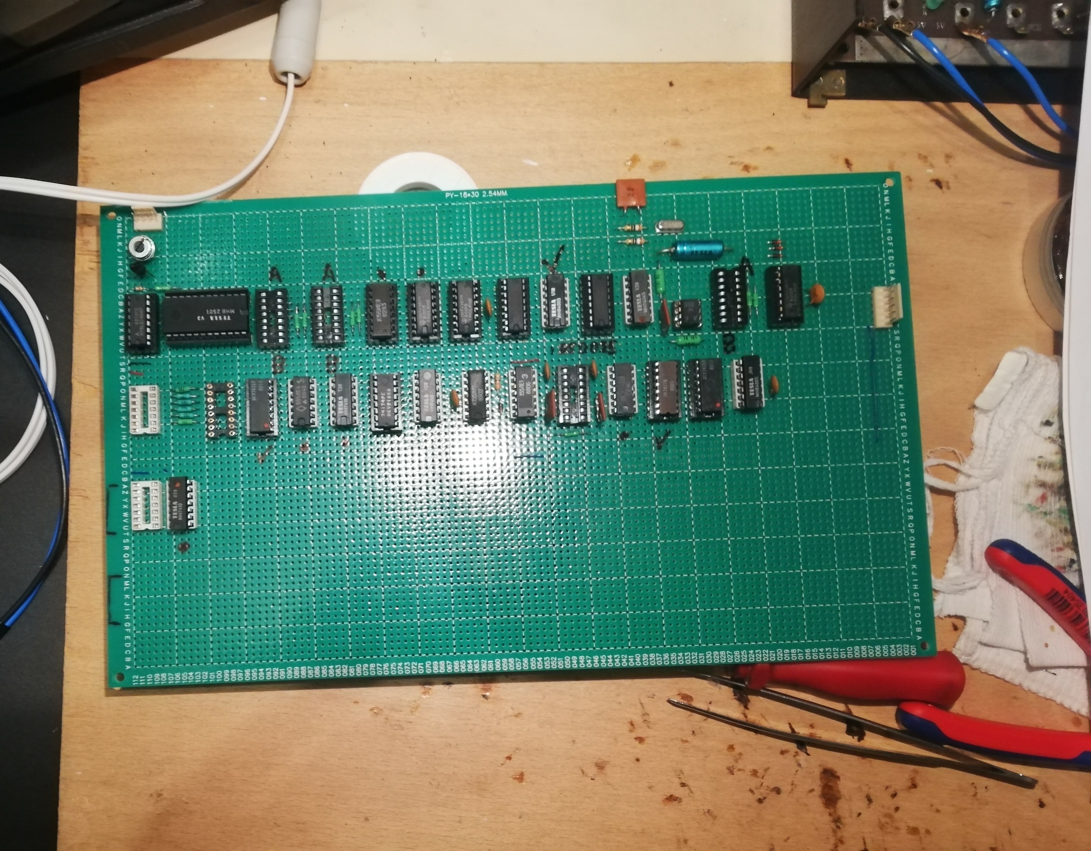
The main thing, that makes my replica hard to troubleshoot is that I built it on an universal PCB, wiring every connection by hand and using a mix of Czechoslovak (TESLA), Soviet and some western TTL chips (similar to this one https://www.applefritter.com/content/apple-i-replica-using-ussr-components).
So, when all ICs are installed (without 2519 and 2504) it dispalys "@" for split second and than the whole screen goes blank. After a while I discovered, that if I remove 7410 at B2, it will display 40 columns of "@" but the rows go to infinity. It might be some vertical sync problem. The monitor I am using is a Czechoslovak Tesla PMD 60, originaly designed to accept PAL composite, but the sync frequencies are fully adjustable by trimmers. I also tried modern LCD TV, which should sync to NTSC and got the same result, so there must be a fault in the terminal.
After some months, I bought an Oscilloscope, so I could make deeper measurments. I measured every signal and found out that a lot of signals got replaced by a weird 15,72 khz signal when the 7410 is installed. I know, that it is an NTSC frequency, but even the outputs of 74161 at D8 are replaced by this signal. So it does no counting and thats why the 2513 (in my case MHB 2501, equivalent from TESLA with different pinout but same functionality) is not displaying anything.
Also, when I remove the character generator, it displays 40 rectangles instead of 40 x 24 small squares.
Things that are not causing the problem:
- filter caps - At the begining I had 0,1 uf and I changed all four to 1 uf - no improvement
- LS, ALS TTL instead of clasic TTL - At the begining, half of the chips were LS or ALS, I changed all to clasic TTL - no improvement
- faulty ICs - It might be possible, but I bought 3 of each chip and changed them multiple times - no improvement
The PSU of my Apple is completly different from the original. I am using a PSU from scraped Czechoslovak terminal, because it has all the voltages needed for the Apple (+5 V, -5V, +12 V and -12 V). Thats why there are no voltage regulators or big electrolitic caps on the PCB.
While assembling, I also kept in mind, that signal VINH and /VINH are the same and that pins 3, 5 on D6, 3, 5, 11 on D7, 1 on D8 and 1 on D9 shouldn't be connected together.
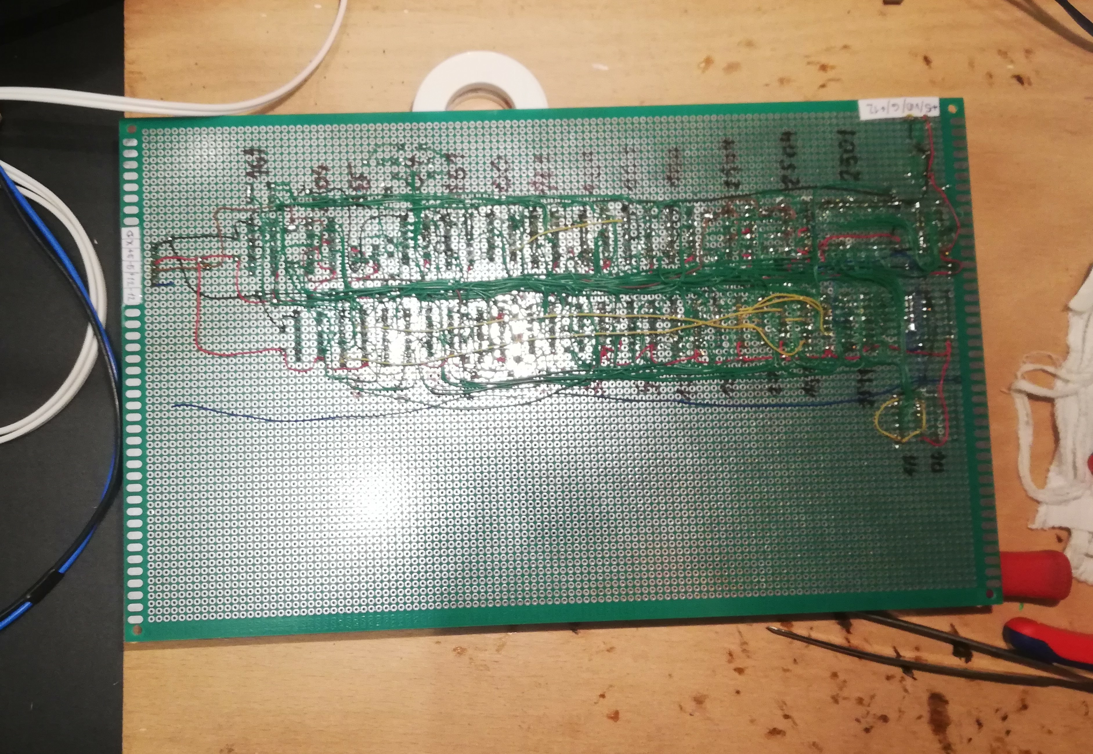
I am attaching some photos of the terminal and the video output.
I would appriciate any suggestions!
PS: I wasn't able to upload the pictures of the video display normaly, for some reason it is blank. Here are some links, that should work.
https://www.applefritter.com/files/2021/06/04/apple%201%20obd%C3%A9ln%C3%ADky_0.jpg
https://www.applefritter.com/files/2021/06/04/apple%201%20zavin%C3%A1%C4%8De_1.jpg
... to ever make your perfboard Apple-1 work are slim (if not zero). But if for some reason or divine intervention (a "miracle") you could make it work, we would like to know !
You should know that making an Apple-1 work robustly is not trivial, even if you use one of the printed circuit boards available. All of these printed circuit boards are equally bad when it comes to power/ground/signal integrity, which is not fault of the purveyors of these clone boards, because they all had to make a faithful reproduction of the PCB layout of the original Apple-1, which even for the wild 1970s is just awful and terrible, although its layout looks orderly and nice, I must admit this in favour of the original layouter. IMHO he is more of an artist than an electrical engineer and so the outcome is no surprise. IIRC, the same person also made the layout of the first Apple-II motherboard which soon later forced Apple (the corporation) to hire real experts to do a new layout which could cope with the FCC EMI rules.
If you use any of the available Apple-1 PCBs and apply my "reliability mods" seen in post #4 of this thread:
https://www.applefritter.com/content/part-path-towards-rock-solid-apple-1-builds
and if you use a known good chip set, that Apple-1 will work well enough to be useful. It will be no worse in terms of reliability than any typical microcomputer of the 1970s. And there will be no more random DRAM corruption and program crashes. It seems I really succeded to "fix the Apple-1", which was my official mission statement and is my "claim to fame". But make no mistake ... even an Apple-1 with my reliability mods still leaves much to be desired. The expansion bus still is abysmal with dubious timing, and the Apple Cassette Interface (ACI) sucks, and is too primitive, having no checksum capability at all, so you can't trust any cassette recordings unless you build a checksummer right into each of your programs, to test itself after startup, and many more little quirks. "Uncle Bernie" is of course working on remedies for all of these ailments, because I need them for my own Apple-1 related work. But don't hold your breath ... with the pandemic winding down and quarantine rules being relaxed, I will devote more and more time into my other hobby again, being an aviator.
So what could you try to salvage your perfboard project, if you wanted to try it at all. If I were in your situation, I'd just buy one of these cheap Open Source Gerber based "Replica-1" PCBs our friends in Russia have provided to the Apple-1 community, and then build an Apple-1 on this platform.
But if you absolutely insist to salvage your perfboard project, you need much better power and ground grids with sufficient power supply bypass capacitors. It is infeasable to improve the power / ground grids by using these thin wires - that is simply against laws of physics. Many hobbyists think that it is possible to construct computers using point-to-point wiring because they saw examples of industrial Wire-Wrap boards or handwired prototypes, but what you typically can't see on these photos is the ground and power planes in the PCB they use. This was a common feature in all Wire-Wrap perfboards and so you could get good power and ground integrity and also add power supply bypass capacitors. You would just solder them in at strategic places and then solder a small dot of solder on each ground or power pin of each IC "socket" to the appropriate power or ground plane. For other prototyping systems they sold power / ground strips which you would glue to any perfboard having no ground or power copper planes.
This is what you could try to salvage your perfboard project. Cut some long strips off copper clad circuit board (no less then 5 mm wide) and glue them on your board so they will run along the IC rows and then use them to connect all VCC and GND lines of all the TTLs to these strips. Put some additional ceramic 100nf bypass capacitors on each VCC/GND strip pair and a 10uF or 22uF electrolytic capacitor on each row.
This is the best you could do to get useful power / ground grids on any perfboard project which has no such power / ground grids built into the board.
But there is no guarantee that it will ever work ! Still, it would be an interesting experiment, and the added time to waste is maybe one of two hours.
For the -12V, -5V and +12V supplies to the shift registers and the character generators (and the DS0025) you will not need such strips, but you still need a 100nF bypass capacitors from each of these supply pins to the nearest ground strip.
If you try to do that, we would like to see your results here on Applefritter in this thread, regardless if these results are good or bad. In any case the Apple-1 user community would gain another "data point" and we could then wonder how the hand-wired prototype Woz had built ever did work.
Maybe he did use some of these prototyping PCBs with built-in power and ground rails. And also note that in the photos we can see it was very, very compact with the shortest possible wires, and not spread out like on the production PCB.
I will respectfully disagree on this one...
I think your chances are quite good, provided you follow through on good building practices.
Woz built his first Apple 1 using point to point wiring and was able to prove the design before making a PCB out of it.
I commend your effort here. I was thinking of doing this myself when things settle down. I have a good amount of
Bishop Graphics Circuit-Stick I'd like to use up and I think this would be a formidable project to undertake with it.
Keep at it and don't be discouraged. UncleBernie has some good tips regarding robust grounding and power, but I
think you can make it work if you're able to identify the issues. Getting "@" to display correctly is a good start.
Hi,
thanks for your replies.
I know that it might be a waste of time, but I will try my best to get it working.
I was really happy when I saw it displaying "@" for the first time, even when it was working just partialy. Because I confirmed, that you can substitute a rare Signetics 2513 with fairly common and cheap (here in Czech Republic) Tesla MHB 2501.
I also plan to install 7x HEF4557 1-64 bit shift registers instead of Signetics 2519, because it is also unobtainium for me. I contacted nearly all electronic online stores in Czech Republic, but nobody had it in stock (For some unknown reason, one shop had 3 pieces of ceramic MK4096 RAM chips for decent price. But I still can't use them, because I need at least 8 of them, so I will build my Apple using 4116 RAM chips.).
Do you know about any shops in Germany or anywhere else in Europe, which have Signetics 2519 in stock?
As for the fault in my system, I made some more measurements today and it must be something with the vertical frequency of the video output. It looks like the 74161 at D8 doesn't know when to stop couning, so there is like infinite number of rows. When i disconnect the PE (pin 9) on the 74161, it will display the infinite number of "@" even when the 7410 at B2 is inserted in the socket. The output (pin 9) of 7432 at C9 is 60 hz signal when disconnected from the 74161, but goes to 15,72 khz when connected.
The fact, that a lot of signals like /VBL are fed back through other ICs to the ICs which generate them is also complicating the troubleshooting process. It is like a chain and the fault is hard to isolate.
This page http://neil.franklin.ch/Info_Texts/Apple_1_Hardware_und_Software.html is helpful, because it explains how the terminal works. But it doesn't show which frequencies should be at a specific locations.
The power rails could be the problem and I will probably replace the VCC and GND rail with a coper wire. At least, I could tell, if it was the problem or not. But I still think that it is just a wrong connection somewhere on the board.
If it helps you any, a buddy of mine built a replica a few years ago using Soviet components, but with 2513 and 2519. Here's a picture if you're interested. Good luck!
IMG_20190709_094134.jpg
If it helps you any, a buddy of mine built a replica a few years ago using Soviet components, but with 2513 and 2519. Here's a picture if you're interested. Good luck!
IMG_20190709_094134.jpg
Macintosh_nik,
thanks for the foto, the board looks very interresting with those green electrolytic capacitors and all the soviet chips (especially the ceramic CM602 PIA).
It is a shame, that Pravetz or Kvazar didn't clone the Signetics 2519 or the Signetics 2504. At least, Pravetz made the CM630P (6502 clone) which I will install in my Apple, if I ever get it running. There is also a second eastern clone of the 6502, the K602BM1, but it is super rare.
I checked the whole terminal today with a multimeter for any cold or wrong connection, but I didn't find anything. All the wires were connected to the pins described in the schematics. So I am wondering, if there are more errors in the terminal schematics, other than the VINH, /VINH and those reset pins on the 74161s which arent wired together.
Then I removed the thin power rails and started replacing them with thicker wires. However, the bottom side of the board is full of wires and it would make any maintenance difficult if the thick wires were in the way. So I will install the power rails on the top and then pass a wire to the bottom, through a hole next to each socket.
I would also appreciate, if anybody would be so kind and measure some of the signals on his own Apple and then send them on this thread. Then I could compare the signals to signals on my Apple and check if they are the same.
Thank you very much for any advice, it helps me a lot.
Hi,
I did it 12 years ago, so it's definitly possible!
You can see the board here :
http://applethefirst.blogspot.com/p/apple-1_03.html
I started this project because nobody was selling replica boards at that point. Mike Willegal was working on the mimeo and the obtronix boards were not available anymore.
It was my first electronic project and the wiring is not very clean. I should have used different colours for sure !
I made only 4 or 5 mistakes but it took me a long time to find them and to debug the computer.
I don't know if you use the schematics of the manuals but there are some mistakes in these if I remember correctly.
You need to put extra decoupling capacitors (have look at UncleBernie posts and Mike Willegal site).
You need to use thicker wire for the ground and the power lines.
Apple 1 wire wrap.jpg
It's still running! I'll do a video soon.
Aurel