
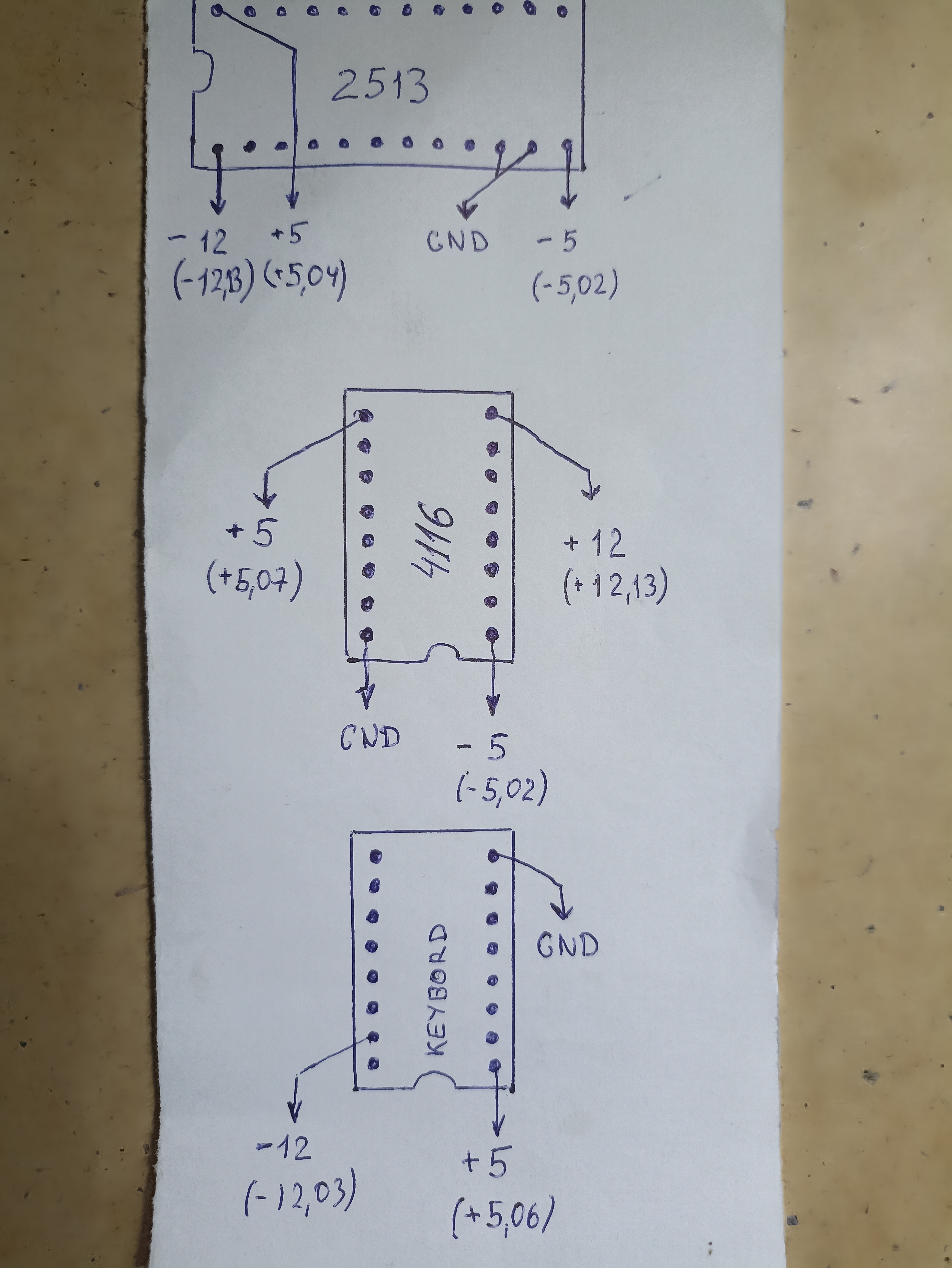
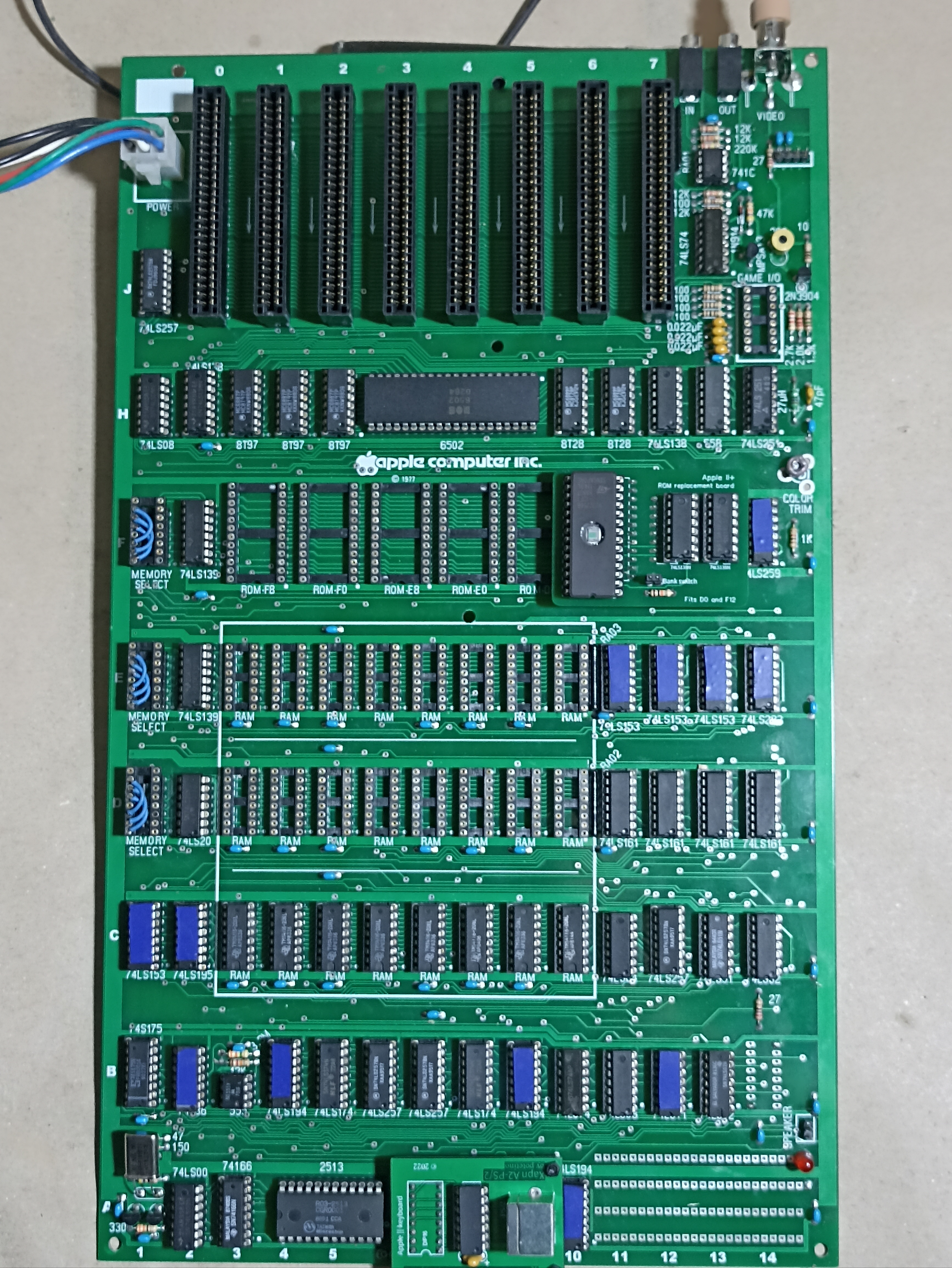
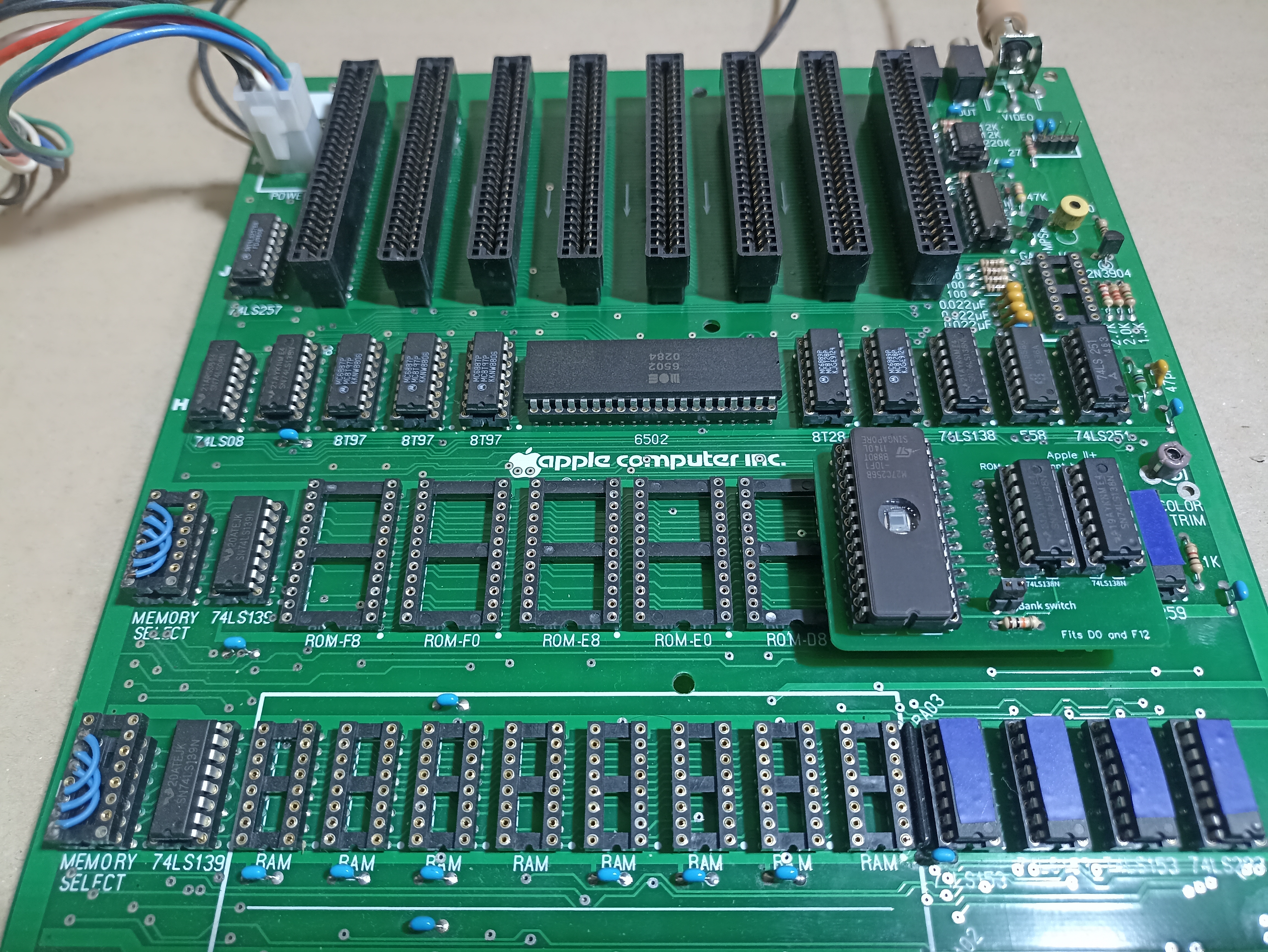
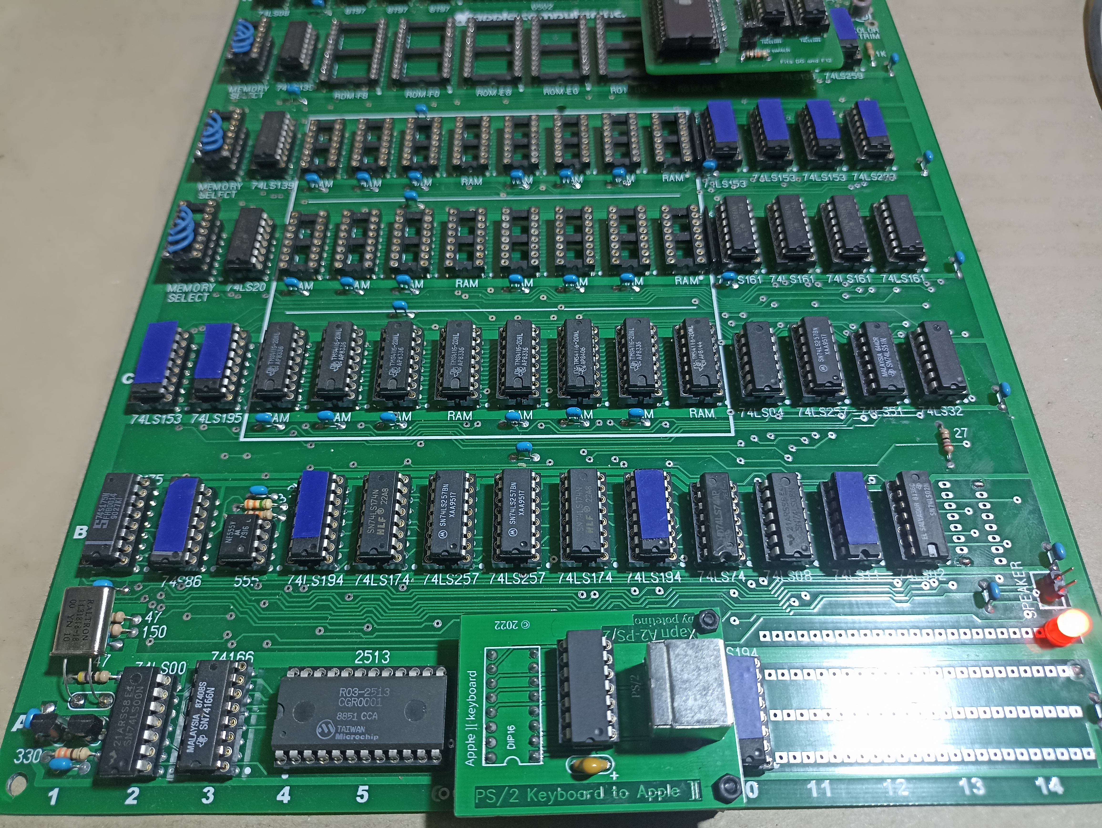
Hey guys!!! I got my project to create a replica of Apple II Rev. 0. Briefly what I used: power supply RQ-65B, board from the project of the respected Mike Willegal, Apple II +ROM board replacement, all components except what I have left after the assembly of the replica Apple-1 I bought on Aliexpress. I know it's not the best option, but now for me because of the imbargo only such conditions, there are no others. Those chips that I couldn't check on my other computers or cards are taped with blue tape, they could potentially be the source of my problems, there is a lot of junk sold on aliexpress. All chips correspond to the silkscreen on the board, no other series or soviet chips I used.
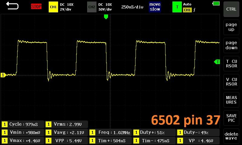
What I have now: the soldering is perfect, I have the correct voltage on all lines, there are no shorts and nothing is getting too hot or smoky, which is good. I also have a signal from pin 37 6502 which made the guy who helped me very happy. But I'd like to get this thing fully operational....
In many ways I am the source of my own problems: I had a great Apple II plus but I sold it to buy an early revision Apple II. But I didn't have the time, because of eBay's politics it was closed for a long time for me. So having a successful experience of assembling a replica Apple-1 I decided to go down the same path, but apparently overestimated my strength....
I will be glad to any help in diagnosing my board.
Have you got video? Show us the screen.
Have youy got a beep?
Have you got a 14mHz at B2?
Have you got the 7 mHz video sync signal there as well?
It would be great if you could insert an F8 autostart ROM and see if it works that way.
Also, I'm curious - what is the blue tape on some of the chips?
Thanks for the help! Nothing on the screen, no sound either, I connected the speaker from my Apple //e. I don't think it's related to my monitor, I've plugged my Apple-1, Apple //e, //c and //gs replica into it and always got a picture.
Can you tell me how I should measure 14 MHz on B2 and whatever else, I'm not really good with an oscilloscope but I have one.
I have this card, I have never used it, I don't know if it works or not. If I understand you correctly I need to get something out of it and put it in my replica. What's that?
I'm sorry, I'm very bad with the Apple II.
The blue tape I taped over the chips that I unfortunately couldn't test. Everything else I checked and they work 100%.
1978 Apple ROM Card.jpg
What is the make and model of your oscilloscope? I want to see if it has a built-in frequency counter. If it doesn't, you can still measure the frequency of 7M on the Apple II bus (pin 36) and multiply it by 2, but it's not going to be very accurate. The idea is to see if the oscillator is running.
Hi, thanks for responding!
My oscilloscope is a Finirsi 1013D.
https://sl.aliexpress.ru/p?key=uYs7Omu
No frequency counter, but you should still be able to measure the 7M frequency to within a couple of kHz.
I'll try to measure tomorrow morning. If I don't understand what values to set on the dipstick and oscilloscope can I consult with you in private messages or on FB if it is convenient?
I would please ask you to write here. Every question and answer will be written here and other users could help them. It has helped me a lot to read old posts, I have learned and I still learn from you. Thank you so much.
Macintosh_nik wrote:
I'm like a monkey with a grenade, but if I'm given the settings I can definitely handle the changes.
You are not the only one, I also include myself. I liked that expression, I will add it to my favorite phrases.
No video at all means there probably no clock signal to the video generation circuitry. I asked if you had any video at all because it's important to know where the problems lie. Often troubleshooting stalled CPU issues you still get video signal onto the screen - like garbage characters or a screen of all white, or SOMETHING.
Having zero video is important because it means either there is a cataclismic failure of the video circuitry or there is not clock signal at the video circuitry, which is more likely.
No beep means the CPU did not start reading RAM and ROM and could not execute any code. Reasons could be many, but if there is no 1 mHz clock signal, nothing happens.
You need to start at the beginning, which is a healthy clock signal. Do nothing until you are certain you have the correct clock signals. 14 Mhz, 7 Mhz, 3.58 Mhz, and 1 Mhz, both phases (one is inverted at the CPU)
Then you can start poking around with ROM and RAM addressing.
That ROM card you show contains an F8 ROM. With it inserted in the F8 position on the motherboard you can basically go back to the "beginning" and possibly eliminate any problems the ROM Replacement Board might be causing. Also, the EPROM on the ROM Replacement Board has an exposed window. Is it programmed? If so, put a piece of opaque tape over the window to prevent intrusion of UV light which may partially erase the EPROM.
The clock timing circuit starts with the crystal and the chip at motherboard position "B2", and is distributed as shown in the diagram. You should refer to the Rev-0 schematic to see what parts of each chip do what, and what pins contain each signal. This diagram shows which chip locations to look at: B1, B13, C1, C2, A2.
Chip designations are as follows:
86=74S86 (Note this is NOT a 74LS86 chip, it is a 74S86 chip. They're similar, but the 'S86 has a much higher current output than the 'LS86.
175=74LS175
195=74LS195
02=74LS02
00=74LS00
153=74LS153
clocktiming.jpg
Folks, please don't overlook the evidence Macintosh_nik documented in the OP!
About RESET in the Rev. 0 board:
When you turn on a Rev. 0 Apple ][ (without any peripherals) it will be frozen until the user manually generates a RESET signal.
Here are some ways to generate a RESET signal:
Keyboard RESET connections.png
About those timing signal measurements...
Here's the oscilloscope measurement of the phase-1 clock from the 6502's pin 37. In addition to showing the shape of the signal, this oscilliscope automatically displays a lot of measurements at the bottom of the screen -- including the measured frequency of the signal.
Osc 6502 pin 37.png
From that single measurement, we can infer that the timing generator is emitting the correct signal from pin 7 of the LS175 at motherboard location B1. That suggests the 14 MHz clock, oscillator, and crystal are all working correctly too, so I've highlighted them in green. To verify the rest of the signals, connect that oscilliscope to each of the identified pins and read the "Freq:" measurement.
Timing generator.png
Good point about the oscillator already running, but I don't think the issue is lack of reset at this point, since his video is not working, which should start before the reset.
Yes, my point exactly...
And, @S.Elliott: good point about the reset.
Then let's inquire more precisely what Macintosh_nik meant when he wrote "Nothing on the screen" in comment #3. That might mean that it's not generating any video signal. Or it might mean that there's a good video signal that just happens to be empty, which is exactly what would happen if the LS194 at A10 is a fake or counterfeit part. (The OP raised the issue of "junk sold on aliexpress" and marked unverified/untested parts with blue tape . . . including the LS194 at A10.)
To Macintosh_nik some clarifying questions:
Thanks to everyone who responded, I really appreciate it.
When I connect the board to my monitor it still says "No Input", I added a picture. I tried to see the signal from the RCA connector of the board, it seems to be just not there! I will also add a photo, in case I do not connect the oscilloscope correctly.
I'm a bit confused, all these frequency measurements from pin 9,2,6,7 and 15 should I take from B2 (74S86)? Thanks in advance!
IMG_20240213_114132.jpg
IMG_20240213_113718.jpg
Yes. Those are the frequencies you should be seeing out of the 74S86's pins.
You should follow them out to where they belong at the video circuitry and to the CPU. And verify that you have 1MHz at pin 37 of the CPU along with pin 39 and pin 3.
You should also follow @S.Elliott's advice about causing a momentary RESET condition after power up to start up the CPU.
1.jpg
IMG_20240213_160839.jpg
Today I tried to make measurements on 74S86 (B2), and at the same time on 74S175(B1) - because 74S86 has only 14 pins, there is no 15th pin. But unfortunately in the Freq column there were always zeros. Then I decided to measure pin 37 6502 but there was also zero. I tried again all three crystals I have but nothing changed. Apparently this screenshot was left in the oscilloscope from the time of debugging the Apple-1 replica and I mistakenly posted it above. I apologize again, I had no malicious intent, I just mixed up the files when I copied the screenshots from the oscilloscope to my laptop. Looks like none of my three crystals are working in the Apple II replica. Now I see why there is no video or sound... I measured all the voltage circuits just in case and they correspond to what is written on the sheet, photo of which I posted above.
There is a spoonful of honey in this barrel. I remembered that when I was debugging my Apple-1 replica, one guy advised me to do a simple test. I had to connect a multimeter to pin 40 of 6502 and GND, and when I pressed Reset +5v as if reset and then reappeared. I decided to try the same thing and it seems to be fine. Apparently this chain of PS/2 keyboard and adapter works and when I solve the problems with the crystal it won't be a problem. I'll add a YouTube link if anyone wants to see it.
https://youtu.be/NEhb9p3PRnU?si=vTL4SSFu9kyFuPjD
"pins 9,2,6,7 and 15" refered to above are on the B1 chip as you discovered. It is possible the XOR gate at B2C is bad - in that case there would be no signal to probe anywhere else down the clock chain. You could try looking at B2 pin 10, but I don't know how badly the oscilloscope probe capacitance will affect the oscillator. Testing B2 off the board should be fairly simple if you haven't done that already.
If you have time while waiting for new crystals to arrive, you could compare your oscillator circuit to the one on the Apple III schematic. It is very similar, but a few resistor values are changed, the base of Q1 is biased differently and there is more feedback between the base of Q1 and Q2. (If I was doing it, I would build the oscillator on a bit of protoboard so I could swap crystals and maybe part values around easily.)
Full disclosure - I don't have an Apple II, I'm just going by the kicad schematic. I do have and Apple III, but the only schematics available for that are the hand-drawn ones from 1980 that may not be too accurate. I have been following your progress in this thread with great interest. Best of luck!
A lot of threads and posts have been written about the infamously problematic two transistor crystal oscillator of the early Apple II.
APPLE (the company) had the luxury to be able to order custom made crystals - just the right type of crystal - to work in their terrible circuit.
See posts #3, #4 and below for this thread:
ttps://www.applefritter.com/content/wanted-apple-1-owners-frequency-counter
Don't get confused it's for the Apple-1, which has an even worse TTL gate based crystal oscillator circuit. The issue with both types of oscillators is the same. They are meant for series resonant crystals while most crystals sold are parallel resonant. These will not work on their specified frequency if put into an oscillator meant for a series resonant crystal. And being off frequency commonly leads to startup problems. You can try to add a small trim capacitor of 47pF max in series with the crystal. This would allow you to tweak a parallel mode crystal to the right frequency even when it's in a series resonant oscillator. It's not guaranteed to work but worth a try.
If you decide to order more crystals you can order one of these DIL-8 or DIL-14 metal can crystal oscillators like this one:
https://www.digikey.com/en/products/detail/ecs-inc/ECS-100A-143/20509
These are not much more expensive than crystals and are guaranteed to oscillate at the frequency that is printed on them ! No surprises !
This is why even APPLE (the company) did use those in the later Apple II models (i.e. IIc) --- seems they were fed up with all the problems caused by their primitive two transistor oscillator. Which, if it works, won't work for all too long because it overloads the crystal. Which greatly reduces its lifetime. This is the root cause why so many people compain about crystal troubles with their Apple II - they found the crystal is dead and then tried to replace it. With the wrong type, of course. The right type (series resonant) must be custom made ... unless you are super lucky and find the random bag of series resonant 14.3181818 MHz crystals in a bag in some electronics surplus store. I never had that luck.
- Uncle Bernie
Let's not sidetrack the problem with the crystal discussion at this point, since the oscillator is clearly working at a frequency that should produce at least a monochrome video signal.
Having the correct crystal and adjusting its frequency is only critical when trying to get an NTSC color image and that comes much later in the game, when everything else is working. The crystal frequency may be way off and you would still get a monochrome composite image. For example the Apple II Europlus uses a 14.250 MHz crystal.
In post #20, CVT wrote:
" ... since the oscillator is clearly working at a frequency that should produce ... "
Uncle Bernie comments:
Ooops ! I was misled by the two photos in post #14 showing a flatlined clock input on the 6502 and a bunch of crystals. This deceived me in thinking the oscillator doesn't work.
Agree that any clock near 14 MHz should produce a video signal. Unless the trim pot is turned down to zero or something else upstream does not work.
- Uncle Bernie
Uncle Bernie, thanks for your help! But a little confused, my crystals in the shiny metal cases work perfectly in the Apple-1 replica, and the gray one I got from you a few years ago and in your link you write that these crystals are closest to the desired oscillation frequency when installed in the Apple-1. Maybe the problem is not in the crystal at all?
CTV thanks for your help too! I just got an email from a buddy of mine, he says he never got a color image on his Apple II Rev.0. He ended up building an RGB card that he could use to get a color image. Here is the video he sent me.
https://youtu.be/DXzW0kvdW9Q?si=IooP8xZPr3itsDLU
Anyway guys I need some kind of plan for tomorrow, where to measure what to measure to see if my problem is a crystal or something else. Thanks in advance!
In order to know where to measure, you need to follow the schematic for the computer.
All the information is there, the chip locations and the pin numbers.
Start with this - print it out and paste it together with tape.
And the clock starts here at the lower left at XT0001.
clock2.jpg
You'll notice the crystal oscillator enters B2 at pin 10 and exits at pin 8. This should measure the nominal 14 MHz.
It then enters B1 at pin 9 and exits at 14, 15, 12, 3, 10, 7 and 7 in varioius divisions of 14 MHz : 7MHz and 1MHz. You should be able to detect all those at B1.
If you look up at the top left you can see lines for 14M, 7M, ø1, ø0 and what pins they connect to.
The schematic is here: https://downloads.reactivemicro.com/Apple%20II%20Items/Hardware/II_&_II+/Schematic/Apple%20II%20Schematics.pdf
If you are sure your crystal is nonfunctional and want a known-good crystal I have one. Message me.
Exact.As soon as I turn on, in my replica I see on the junk screen.There is no whistle.
Basura en pantalla , antes del reset
When I connect Pin 3 and 8 ... then it starts.
pin 3 y 8
I recorded this video the first time it was put into operation.
Primer encendido Apple II Replica
I see you use an Ikegami. good choice.
I also use a similar monitor, from another brand.
Are called .. PVM?
Here we call them "Surveillance Monitor" or "Security Monitor"
In the rest of the monitors and TV I have not been able to see anything. I know without seeing anything.
I can see Apple1 Replica in almost all, even on the new tv 46" MI
I have been fortunate to make both the ECS 143-S-1X and CTS MP143 work with reasonably matched PN4258/PN4209. They are available from several distributors. Transistors are another story. Many of the A2 clone and replica repairs i've performed for others found random 2n3906's in use.
On several clone motherboards where the oscillator layout on the PCB was less than optimal, the ECS 100AX-143 DIP-14 oscillator ended up being the best solution. It just always works. I use them just to inject 14M into boards during diagnostics.
The first things to check when diagnosing any vintage computer are always, voltages, clock, and reset. You don't need to look any farther until you have those.
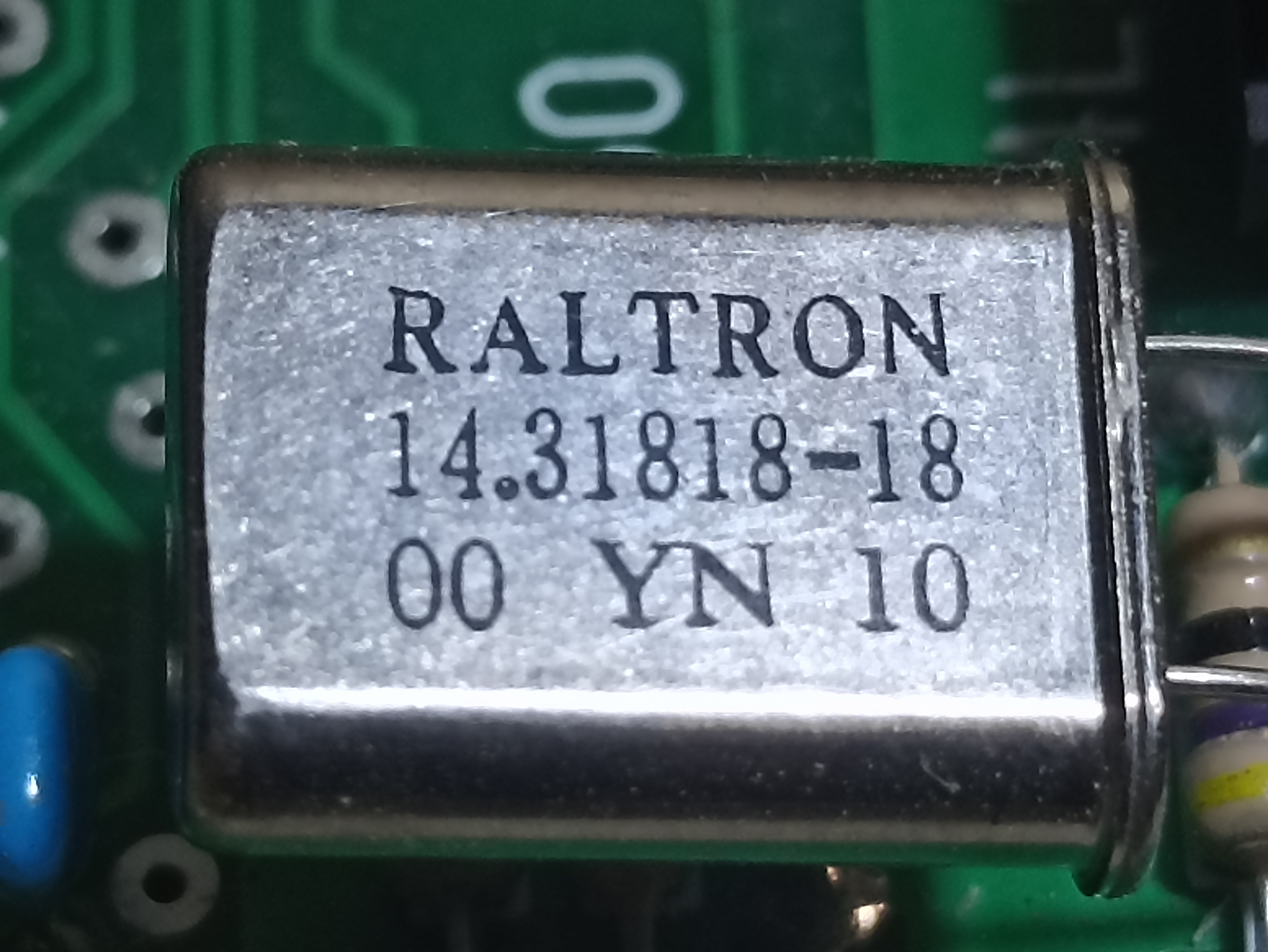
The Nymph NMP143 crystal in your photo is series resonant and should work if not damaged. The Raultron crystal is the incorrect type (18pf parallel) and will likely not work, or may be off frequency if it does work. The smaller HC-49/U crystal looks like it *could* be a CTS 14.31818MA, which is also incorrect as it is 20pf parallel.
If you have a working oscillator frequency close to 14.31818MHz the machine *should* at least execute code (but don't expect frequency dependant functions like NTSC color to always work).
Today was a real breakthrough!
But it didn't start well, I tried to read 75S86 pin 10 with an oscilloscope, but unfortunately I didn't find anything encouraging. Sometimes some numbers appeared in the Freq column, but then went to zero again. And I was supposed to see a steady 14.3MHz signal, wasn't I?
Then I decided to trust my intuition. Since there are two 2n3906 transistors in this circuit besides the crystal, I decided to change them to other ones. And it worked 100%!
I found a stable 14.3MHz signal on 74S86 pin 10, and also that the No input sign on my monitor started to twitch a bit. I twisted the 200 ohm trimmer a bit and got some garbage on the screen. I have video!
Next I moved all the big chips from my ROM card and when I pressed Reset, in my case it was a combination of CTRL+ALT+DEL on the PS/2 keyboard, I heard a squeak in the speaker from Apple //e. I have sound!
I then tried typing HELLO WORLD! and again good luck, my keyboard and ROM chips are fine! Not bad for a plumber?
I know there is still a lot of work ahead, the picture is not stable, no color and once in a while when I press Reset it just disappears but I think with your help I will manage to debug it all.
Unfortunately in Russia this hobby is not very developed, no, other guys of course also collect replicas of Soviet computers, mostly ZX Spectrum clones, but in Apple almost no one understands. I have no one to consult with, so all hope for you guys.
Below you can see 3 screenshots and a couple of links to YouTube videos of today's results. I need a plan for tomorrow. To everyone who is helping, thank you very much from the bottom of my heart!
1.jpg
2.jpg
3.jpg
https://youtu.be/Q02p1nFvapI?si=oMZfOWWmOj1rTXxZ
https://youtu.be/0C-J3i-18fo?si=rxR10lBtbt9eaEL-
In post #28 "Macintosh_nik" wrote:
Then I decided to trust my intuition. Since there are two 2n3906 transistors in this circuit besides the crystal, I decided to change them to other ones. And it worked 100%!
Uncle Bernie comments:
See, after all it was the crystal oscillator refusing to work, so my post #19 was right, and "CVT"'s rebuttal in post #20 was wrong (it still eludes me how he came to the conclusion that Macintosh_nik's was "clearly working". But it could be that the oscillator did work ... sometimes. And other times it didn't work (Startup problem). Which would explain the confusion very well.
The bottom line is that if an Apple II appears to be "dead" despite all power supply voltages are in spec, the next step should be to see if the crystal oscillator does oscillate or not. For that, the poor fellows with no money to afford an oscilloscope must use / build a "logic probe pen" which not only has a LED for "Low/High" logic level, but also a LED for pulses. These can be built for less than $1 in materials if a discarded / empty marker is used as an enclosure. Use the "fat" markers (Such as "Sharpie Accent Highlighters") because their inner diameter is large enough to shoehorn a DIL-14 IC into it. With the smaller diameter pens you would need to use small SMD parts.
- Uncle Bernie
P.S.: the measurement of 978ns indicates that the oscillator runs at 14.315 MHz ... if we calculate for 977ns and 979ns boundary cases, this is 14.32958 MHz and 14.3003 MHz (take the reciprocal of the time period and multiply with 14 --- the number of M14 clock cycles per CPU cycle). The reason for the +/-1 ns cases is the (unknown) actual time resolution of the oscilloscope, and the unknown accuracy of its internal timebase.
The wanted oscillation frequency is 14.3181818 MHz.
So you might need to add a small trim capacitor (5-47pF) in series with the crystal to be able to tweak the frequency to the correct value, at which the NTSC colors should appear. (See the link for the frequency counter thread in my post #19 above, to see numbers at which the colors appear and where they disappear. Your monitor may be slightly different in which frequency band for the color subcarrier it accepts, but the message is that if the frequency is off by too much, there is no color).
The conclusion came from the incorrect screenshot posted in the very first post of this thread showing a working oscillator and a 1.02 MHz square wave.
I'm very happy to hear it.
What crystal have you used?
Can you upload a photo?
Now for the color it would be easier to use a parallel crystal + a trimmer capacitor, instead of trying to find the correct serial crystal. This is the one I used in my Apple II+, but any parallel crystal of that frequency will work. The capacitor is from an old Sokol transistor radio and it is set to about 25 pF:
Crystal.jpg
In post #32, CVT wrote:
"... but any parallel crystal of that frequency will work ..."
Uncle Bernie comments:
Correct. But to avoid any misunderstanding, I meant to put that trimmer in series with the SAME crystal which Macintosh_nik already uses. It seems to run too slow (as far as we can guess from the time period his oscilloscope tells us) and adding the trim capacitor will make it faster. Running too slow in a series resonant oscillator circuit is typical for a "parallel resonant" crystal which by definition are always ground to have their series resonant frequency a little bit lower than what is stamped on them. This allows for additional reactances in the circuit and still get the right frequency which is stamped on the crystal. In this case, the added reactance is the trim capacitor. Sounds confusing ? Well, this is the reason why nobody in the industry dares to design a crystal oscillator anymore, especially if long life and low drift / high precision is wanted. The exception from the rule are the crystal manufacturers who make these little DIL-8 and DIL-14 oscillators (nowadays also much smaller, as SMDs) because they know what they are doing and they can tweak the crystal that goes into their oscillators for all the desired properties in the particular circuit they use. So disappointments and fiddling on the production floor until the damn things work is prevented. Back in the 1950s to the 1970s it was common practice to have adjustment steps in the production process. Nowadays a part must drop right in without any adjustments at all, and do its job and be in spec. This is why everybody uses ready made crystal oscillators nowadays and why discrete crystals are a slowly dying species.
- Uncle Bernie
Many II+ clones, including the excellent Unitron variants had a colour trim "trimpot" near the crystal oscillartor circuitry to adjust the crystal frequency so that the computer rendered colour properly.
And another reason why I hate that the preferred build seems to always be a Rev-0. Rev-0s are challenged in many ways, one of whic being they can only render four colours.
Home replica builds should be a Rev-7 at minimum, and better yet, a 100% clone build like a Unitron clone that could accept EPROMS and had nice features like a trimpot for the oscillator.
Anyway, I tried all 3 crystals with and without tuning capacitor and unfortunately there is no difference. I always get sound when I press Reset, most of the time I get video, but sometimes I have to adjust the 200 ohm resistor a bit. Sometimes when I turn on the power to the board I hear some crackling in the speaker, in this case there will be no video no matter how much I do not twist the resistor. In general the board is definitely emitting some interference, in the basement where I work I always have the radio on, I can clearly hear the interference. Trim capacitor if I soldered it correctly, it doesn't change anything, the image is always shifted to the upper right corner and also has interference. The image disappears either when I press Reset or when I try to enter a simple command L then Enter to display the memory contents. Apparently the computer can do this, but there is some sort of video glitch. I have changed the 47pF capacitor and the 2n3904 transistor in the top right corner of the board but nothing has changed. I found I put the wrong resistor, 2.2k instead of 2k - could this be a problem?
I have a hard time with anything related to electronics, because I do not have a specialized education. Almost never what I build does not work right away. But I am stubborn like a sheep, I can spend hours on a problem until I get what I need. I have attached some screenshots from the oscilloscope, a photo of the board in its current state and a link to a video where you can see how everything happens.
Any thoughts on this would be appreciated, thanks in advance!
1.jpg
2.jpg
3.jpg
4.jpg
5.jpg
IMG_20240217_164228.jpg
IMG_20240217_164118.jpg
IMG_20240217_151622.jpg
https://youtu.be/NIRTCWGcBp4?si=WUB3Jb8U4OpYj-cN
First you need 50pF max variable capacitor in series with the crystal to get a color image. Only then you can use the COLOR TRIM variable capacitor on the right side of the motherboard to adjust the tint of the color image. Looks like you are jumping to Step 2 without having done Step 1.
Adjusting the trim capacitor that you put in series with the crystal is a bit tricky. You have a very narrow position that you need to hit. You need to load up some color program and adjust it while the machine is on. If you go too far in either direction the machine freezes and doesn't boot.
I soldered a 5-50pF trim capacitor on the back of the board, there is a photo above. It's just the same as the COLOR TRIM. I twisted it left and right but nothing changed. I tried this with all 3 crystals. So is this how I stabilize monochrome video?
If it's on the back side, how is it in series with the crystal?
Can you show / draw / photograph how I should solder it? I'm having trouble understanding what I'm supposed to do. Thanks in advance!
Sure, here is before and after:
AddTrimCap.png
This is why it needs to be on the front side, if you don't want to interrupt traces on the motherboard, which I assume you don't.
Thank you, sorry bro, I have to be very detailed. I now know exactly how I should do it. One more question, should I set this up by just looking at the screen or should I use some type of measurement? If so, where and what should I measure? Thanks in advance!
Just have the computer load something with color and look at the screen while you adjust the trimmer. Keep in mind that you might have to reset the machine many times while you are adjusting it, so if you can automate the color image appearing without having to type too much that would be nice.
I hope it's all right now? Is this screen saver supposed to be in color? Can I use it for now? I only have 8 memory chips in row C filled, so I don't think I can load anything via the audio input now....
IMG_20240217_192637.jpg
IMG_20240217_193340.jpg
IMG_20240215_133147.jpg
The way you have connected it looks correct, but obviously the picture doesn’t look right.
I cannot tell you if the image you are looking at is supposed to be in color or not. But you need to be doing this with an image that you are 100% sure it's in color.
What is the model of the Ikegami monitor and does it support NTSC? Also there is this waviness – did it appear when you added the trim capacitor?
Without the trim capacitor does it still look like in this video: https://www.youtube.com/watch?v=0C-J3i-18fo ?
Also I don't know if it's supposed to work with a serial crystal like the one you have right now. The one I have in my machine is parallel, like your Realtron 14.311818-18.
You see parallel crystals resonate at slightly lower frequency, so using the trimmer cap we can raise it to what it needs to be. However if the serial crystal is at or slightly above it, then we cannot lower it using a trimmer capacitor in series. We are only raising it and overshooting even further.
Model Ikegami CMK-1080. I connect Apple //e, //c and //gs to it. I also used to connect my wonderful II Plus to it until I sold it. The picture was always colorful and bright.... I bought all these computers in the US, so NTSC shouldn't be a problem for this monitor.
The picture was and still is after adding a trim capacitor. I twisted a little to the right, a little to the left, but no color. Nothing has changed at all, the picture disappears either after pressing Reset or after L and Enter. Here's what I was able to get once after customization.
I ran out of the house on a Saturday night like Lenin. He told his wife he was going to his mistress, told the mistress he'd be home with his wife. And he went to the library, to work, to work, to work!
I have to go back, we'll continue tomorrow. Thanks for your help!
IMG_20240217_203718.jpg
The composite video signal appears to be missing its horizontal synchronization. This can also happen when the signal level is too low, much lower than 1Vpp. Try to increase it using the potentiometer in the top right of the motherboard.
If you are looking at the composite video signal with your oscilloscope, make sure the monitor is plugged in. If the monitor has a switch in back for "Hi Impedance" or "75 Ohms", set it to "75 Ohms".
Remember how I mentioned Rev 0 boards having issues with NTSC compatibility including sync issues?
Even back in the days of analog CRT monitors the early Apple IIs didn't always work right with every monitor. Later revisions generated better qualty video although no ][+ really was very close to "standard" NTSC. The //e was a little better and the IIgs better still but no Apple II was really ever more than "close enough". If you ever tried to record onto a VCR or even worse tried to hook into a TV broadcast you'll know what I mean. We used to have to use a box made by a company called "Blonder Tongue" (believe it or not, always seemed like a weird name) called a "Broadcast Stadardizer" to filter computer video enough for it to look right on TV. That box cost about what an Apple II did.
You might want to look for the fixes for that. If I remember right there were some posts about it either here or on the Facebook Apple II groups.
Okay, I changed the crystal. Now I get almost the correct picture, but as soon as I press Reset it disappears. CVT's words that the signal to the monitor should be greater than 1 v made me think to see what's going on in the oscilloscope. In general I have a normal signal of 4-5v depending on the position of the trim resistor, which starts to drop below 1v after I press Reset. I tried this with chip F8 on the motherboard, with AppleSoft and Integred Basic on the ROM Replacement card. I also tried it with Dead Test, the video I am attaching should show how the signal drops with the image when doing the test but then comes back. Sometimes it is accompanied by a beep from the speaker, sometimes not.So I think the monitor is not my problem.
Question: is it still the crystal or something else? I'm pretty sure I should try an external oscillator board. What do you think?
Anyway, I will be able to do it in about a month when I get the PCB. So I have another question, I want to order more memory chips... Would the TMS 4116-20NL work for that? I have them now but only 8 pieces in row C. Thanks in advance!
https://youtu.be/tSkB543i8CQ?si=vgr6jiCMUGigSp04
IMG_20240218_111408.jpg
IMG_20240218_113315.jpg
By standard it should be 1 volt peak-to-peak, but CRT monitors like yours can accept much wider ranges. It is impossible to tell from your video what the composite signal looks like on the oscilloscope, but in general it should look like this when displaying color bars:
BarPattern.JPG
Vertical bars are super-convenient for oscilloscopes, because every horizontal line is the same, so it doesn’t matter which one you trigger on.
Some time ago I wrote a very short program in Basic that displays verical color bars on the Apple II: PATTERN.zip
This program shows this on the screen:
Pattern.png
Also in your pictures it looks like the solder joint beween the crystal and trim capacitor is really close to the case of the crystal. Make sure it's not touching it.
I found my mistake, I put a 150 ohm resistor instead of 1.5K, one little stripe on the resistor changed everything! I feel like I'm still 20 years old, but the reality is that my youngest son will be 20 in 3 months and I guess I need glasses :)
Everything seems to be working fine now, video runs smoothly and has color on both monitors. Just waiting for the rest of the memory chips to arrive so I can further test my board.
IMG_20240304_115154.jpg
https://youtu.be/FeX-BGhSJoQ?si=0Ix0yGXYWpS1FLaV
https://youtu.be/_Zi2-aaAW3I?si=CeKXyn04jQcRp50t
Very nice! Since it's a Rev.0, are you planning to add a color killer transistor or the extra color mod?
Pages