Hi Everyone! I just became the proud owner of a beautiful IIci system!
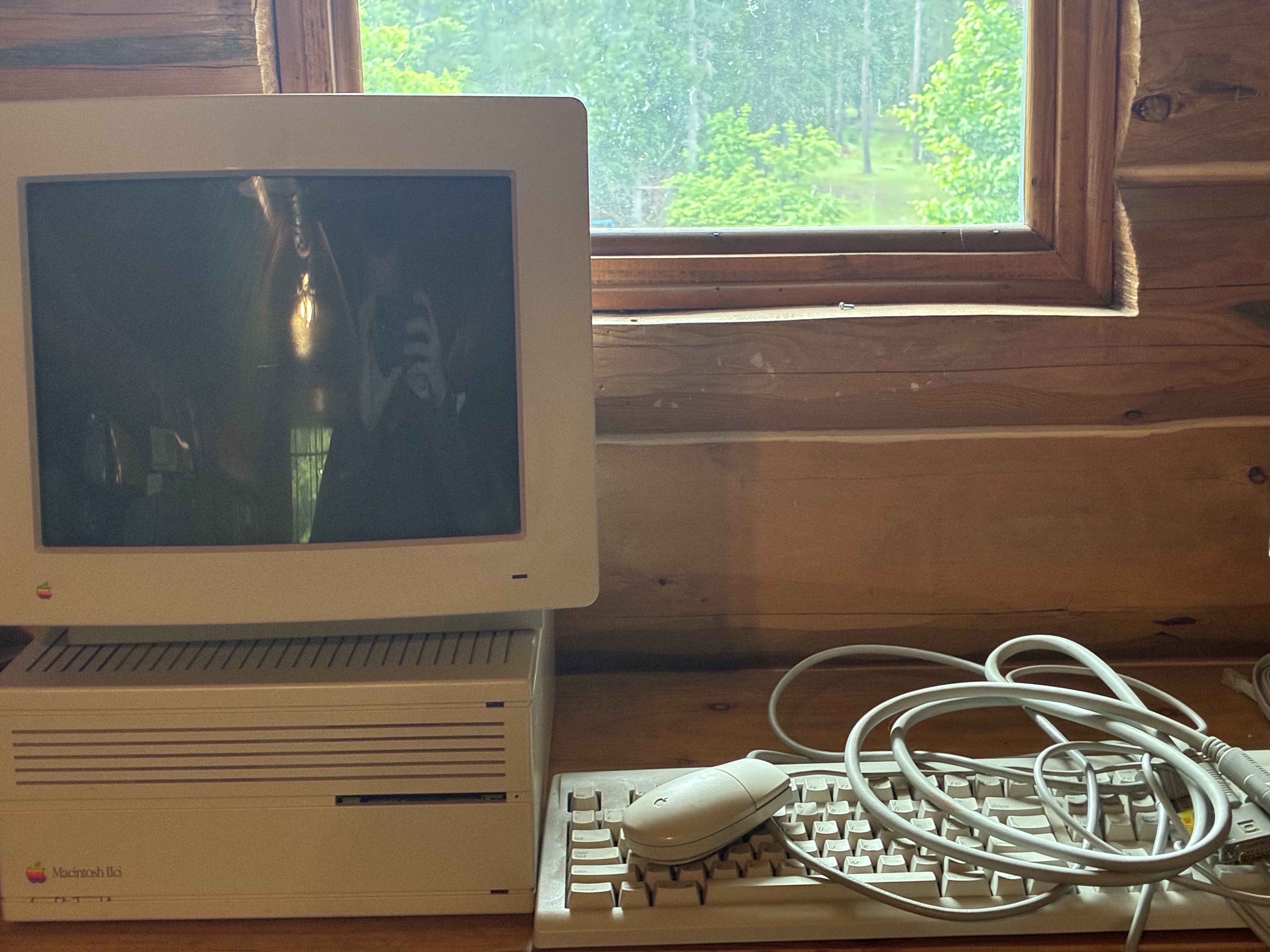
Only problem is - the monitor won't turn on.. I've done some diagnostics over the past few days and believe that the flyback transformer is arcing internally. There is no visible damage to any of the PCBs and during a "dark test" the flyback had a pretty blue glow. :(
If anyone has experience repairing these monitors, I’d really appreciate any help. I've looked on Ebay but found no matches for my exact transformer model: 1-439-497-11. So if you know where I can find one or know of compatible parts, let me know!
If the FBT was really arcing, the cracking or snapping noise would be unmistakably loud and the epoxy would be melted. Just a glow is called corona discharge, and would be expected after the rubber insulation gets dried out and develops tiny cracks. It is simply remedied using high-voltage varnish over the cracks.
See the CRT repair notes here:
Arcing from flyback or vicinity
The flyback transformers cannot be replaced except by scrapping other identical monitors.
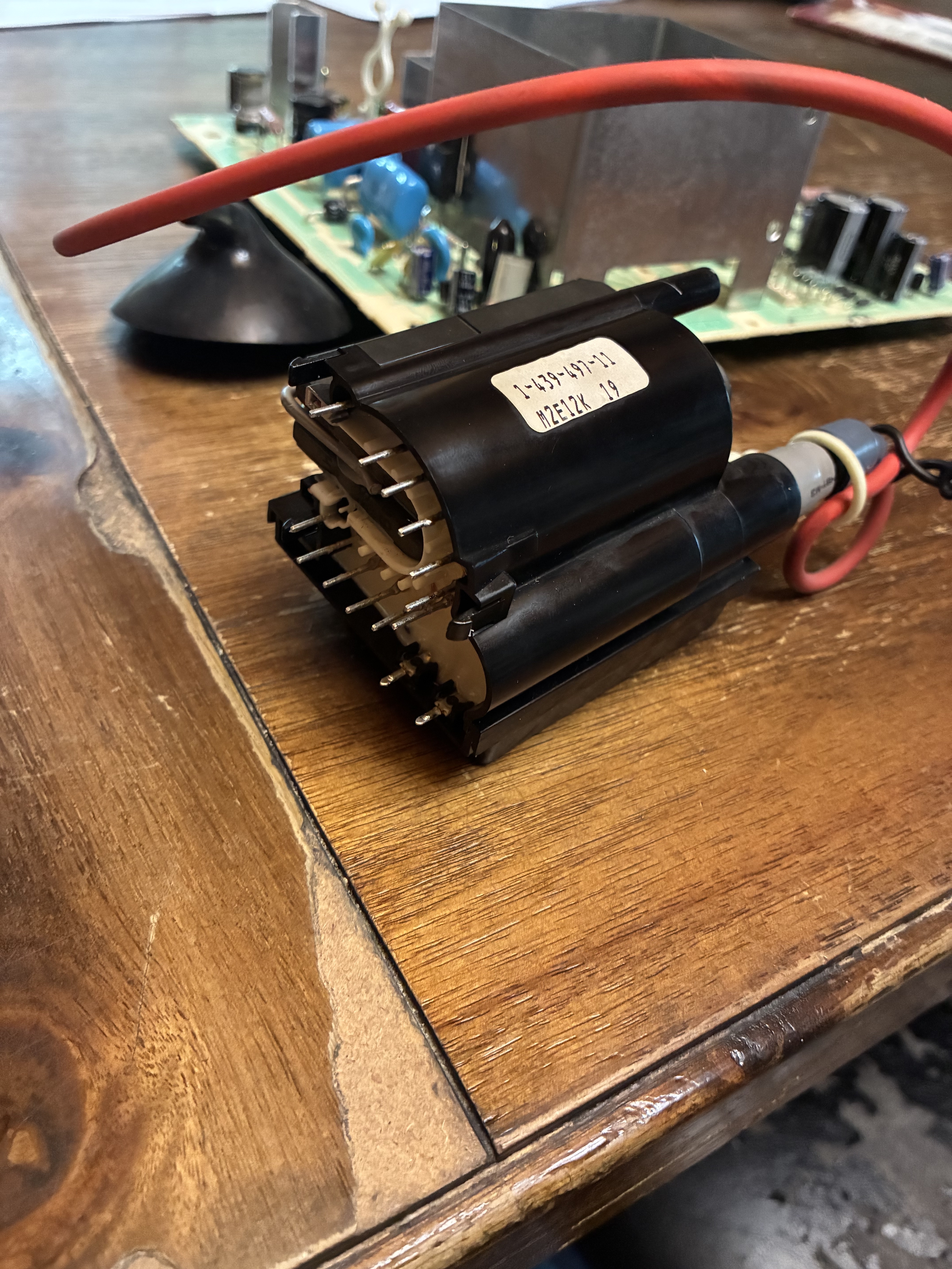
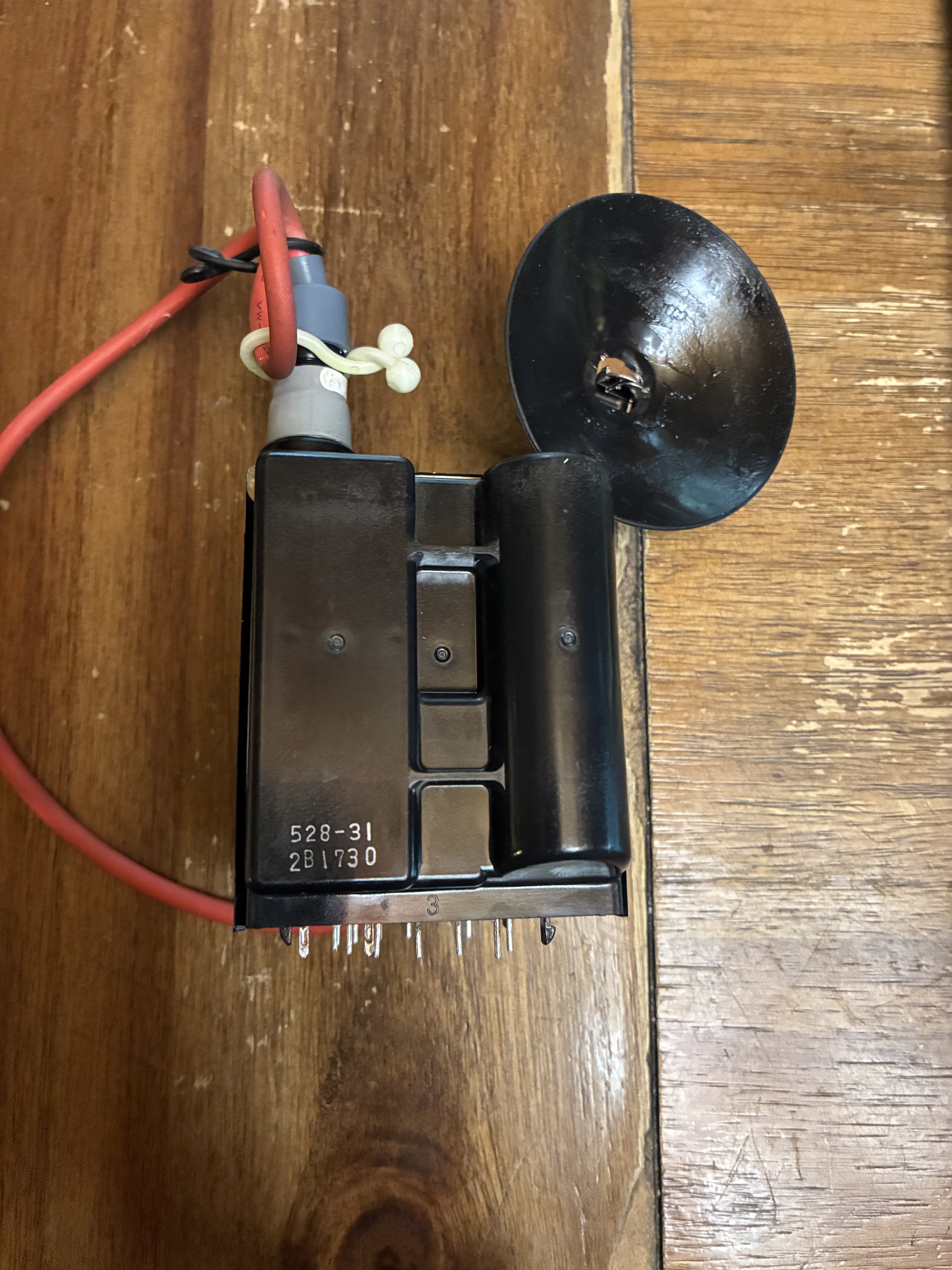
IMG_0662.jpeg
The manufacturer used something called Glyptol to seal under the anode cap, and there is a popular varnish available in small bottles called Super Corona Dope. Any kind of epoxy or neutral-cure silicone could also be used, depending how stiff and how thick the seal needs to be. Is the blue glow actually coming from around the gap where that yellow glue is?
The reason it's important to distinguish corona from arcing is that they indicate different levels of damage. A corona is an electric discharge into space, where the high tension electrode is imperfectly insulated, but it doesn't find a path to short-circuit back to ground, so the current is very low and the temperature is cold.
An electric arc is a very large current and gets extremely hot, hot enough to melt or vaporize most materials. In particular, organic compounds like the epoxy resin in circuit boards burn up, and the carbon soot is conductive, so the arc can continue to move and destroy progressively more of the assembly. When repairing the damage, it's necessary to scrape and grind away any carbon tracks before filling in new insulation. The burning resins also have a terrible smell (which is toxic, I think).
Cool! I have some Corona Dope ordered!
I'm not sure where the blue glow is from exactly. Since I realised something was wrong, I've tried to keep power on to a minimum and didn't think to pinpoint the glow. But I'm definitely sure it is from around the transformer area.
Well, it does look to be corona then because the circuit board and surrounding components are completely free of melting or burning.
Thank you very much for your help so far and hopefully I can make some progress when the dope arrives!
I noticed you also said the display wouldn't turn on: I can understand that there was no picture, but I'm curious if the LED on the front bezel lit up or not? That could point to a low-voltage power supply problem, which sometimes does implicate the FBT. It's necessary to trace power flow through the schematic to see how the different voltages get generated.
I have a few M0401/M1297 monitors, I should test if they still work.
I'm almost 100% sure that the LED was on. Can't say for absolute certain, but I think I remember correctly and probably would have been concerned about the power supply in that case. By the display not turning on, I simply meant that it doesn't display a raster.
Do you think it be worth checking the voltages anyways, just to verify that the FBT is getting the proper supply?
And my insulating varnish came, so I've been coating the transformer's glue - hopefully that'll help fix it!
Not displaying a raster (with brightness turned up) points to a fault in the sync circuit, although EHT or emission could also do that.
If the horizontal output is broken, the flyback transformer won't get the pulses it needs to generate EHT, but your corona discharge would argue that it is working.
Do you have a high-voltage probe? E.G. Fluke 80K-40, or any other? Any reason to suspect the tube (broken during shipping? Is there a spot of "crud" behind the glass in the exact center of the screen?)
The tube itself looks fine, there's no discoloration on the front. I read there's supposed to be a ring that changes color if the vacuum is compromised, but didn't know where to find that. (Any pointers?) So I'm assuming it's ok, even though I haven't verified.
My Fluke is rated to 1000V, so not high-voltage for this case I guess. :D
Do you know of any place that has the schematics for the high-res monitor? I haven't been able to find one, unfortunately. If coating the FBT doesn't fix anything, I'll have to start looking into other components. Hoping it'll work, but you never know. :P
If the vacuum is compromised, you would know right away. This is what a CRT that has gone to air looks and sounds like: https://www.youtube.com/watch?v=AsCBUaKc6VA
I bought this monitor from eBay, but it was badly packaged and it got damaged while being shipped from Italy. Luckily I was able to find an identical tube replacement locally for only 5 euros and now it's my best monochrome CRT monitor: https://www.youtube.com/watch?v=7afJAK1tWxI
Oh wow, that's crazy! My tube does not sound like that, thankfully. :P
That's really lucky you were able to find an identicle tube for so cheap.
I'm going to put my monitor back together later tonight with a newly sealed FBT; I'll keep you all updated. :)
P.S. Sorry about the failed posts above...
Update for everyone!
I got everything soldered back together and tested the tube - no luck. It still sizzles, no raster, and smells weird.
I took a video this time and the sparks don't look to be coming from the FBT actually, but a connector slightly above it. Does that make any sense? Also it looks like there are a couple bigger sparks to the metal frame, but those could just be odd reflections. What do you think?
As for the smell, what I would describe as "odd electrical" the rest of my family describes as "fishy" so I'll be ordering a new cap kit for this monitor. I don't know, maybe my smell sense is bad. :D
IMG_0671.MOV
IMG_0672.MOV
What you are smelling is the ozone that is being formed from the oxygen in the air as a result of the arcing. Breathing it is actually quite bad for you.
You have to find exactly where this arcing is coming from before you can fix it. You are not going to get a picture if all the high voltage is being used to make ozone. If it’s coming from where the red high voltage wire plugs into the flyback, remove the grey rubber cap, unplug it and take a look at what is happening with the connection. Make sure to discharge and disconnect the high voltage wire from the CRT, otherwise it might shock you, which is quite unpleasant (personal experience speaking) and can be dangerous or even fatal in some cases. Once the black cap is disconnected from the CRT, make sure you don't accidentally turn on the power before you have reattached it.
Ok, I figured out a bit more:
There is an electric arc on the PCB "D" between two of the wires going to the deflectoin yoke (I think that's what it is?) SO to repair that, I dremel out the carbon trace so that it no longer conducts - that seems pretty straightforward. My question is, what casued the arcing? Is that someting that would "just happen" or is there a component that died further up the line that casued it? And if so, what parts are likely suspects?
I imagine it'll be more visible after removing the white plug.
IMG_0677.jpg
Yeah, that is definitely carbon tracking from an electric arc.
I will spend a little time searching for a schematic (which is sorely needed here) but one thing I'll point out for now is that that connector has pins for the horizontal and vertical yokes, but also two more pins in the middle marked "D-3". They may be part of a convergence circuit.
Because this display is a Trinitron, there is special magic around horizontal convergence. The anode cables on Trinitrons are coaxial, with both EHT and H.STAT (horizontal static convergence voltage). There is a potted module that derives H.STAT from EHT (or it might be built into the FBT).
You can go ahead and grind off the carbon track (which is required anyway), but deeper analysis will be required to find the cause.
Since the pulses that drive the FBT are commonly (not always) driven from the horizontal output transistor (HOT) that drives the horizontal yoke, this may point again to a FBT insulation failure. But the HOT is always suspect, since it gets driven at the limits. You also need to test the horizontal yoke since it may be open or one or more turns may be shorted.
There's a "Service Source" service manual, but no official schematics that I could find. The 'BOMARC' company did draw schematics for the M0401 (both "Tokyo" and "Nakada" versions), but they went out of business a decade ago, and these seem to be lost.
The service manual does show the H.STAT module I mentioned, labeled "High-Voltage Capacitor", but I don't see it in your pictures, so there may be a different version that integrates it into the FBT.
I might be able to compare the two units in my collection, but a lack of time and bench space makes that unlikely for now.
According the Macintosh II Repair and Upgrade Secrets on page 77, the AppleColor HR RGB monitor is built on the same frame as the Sony Trinitron CPD-1302. Its service manual containing the full schematics can be found here: https://archive.org/details/bitsavers_sonymonitoService_53522054
That information must be regarded as highly suspect, since the High-Res RGB monitor is fixed-sync (640x480 at 66.7 Hz), while the CPD-1302 is a multisync display. The board layout is also completely different, as can be seen by comparing the photo of the yoke socket above with the CPD's:
CPD yoke.png
I could believe that by "the same frame", the author simply meant that the overall chassis design of Sony's 13" 1980s computer monitors is evident in multiple products. But that is of no use in board level repairs.
Edit: I should qualify that somewhat, because I already learned something by looking at the CPD-1302. The yoke connector has six pins because each side of the horizontal yoke is driven by two pins in parallel. The arcing was therefore between the pins that are across the opposite sides of the horizontal yoke.
That is too bad, since it means there a no publicly available schematics for this monitor. Actually, the author says "similar frame". I am not sure how I got "same frame" from reading that, must have NI-hallucinated it!
Hey all!
Just wanted to provide everyone with an update (sorry I've been on vacation and really busy so haven't had much time to play with old Macs :)
After cleaning the carbon trace and putting some HV varnish on the pcb, I deceded to power it on, since I really couldn't figure out anything else that might be wrong... It works! (Honestly I'm not sure why the image is so blue. The colors look normal for me.) What dials would I need to adjust to get rid of the "reflections" on either side? Is that controlled by dials, or pointing to a failed component?Thanks so much for all your help so far! This is really great progress for me!
IMG_0809.jpeg
You need to turn down the SCREEN voltage.