| Attachment | Size |
|---|---|
| 12.41 KB | |
| 37.23 KB | |
| 41.3 KB | |
| 23.72 KB | |
| 15.28 KB |
The 400 mHz Indigo slot-loading iMac refused to start-up. Plugging a monitor into the back didn't work either (a 13 inch Unisys). No amount of button pushing or battery changing was going to revive it. After a lot of research on the web, a solution was found. Major surgery was needed. It is now sitting on a desk, bare and running OS 9 and OS 10.2.5. There is a 2 inch fan blowing on the motherboard to keep things cool. When I can afford it I will re-case it, maybe in a case of my own design.
Here are the two new connectors/boards I used to get it working again. I don't have a digital camera so I scanned them.
NOT FOUND: 1
New Video Cable
The first is the new video cable made from a Mac internal floppy cable, the magnet from the original cable and a new VGA connector with hood. It has worked very well and I haven't seen any color shifting from using the original cable and the VGA connector. I slit the cable between the wires, in the middle in pairs and at the connector end individually. (Based on a PC modding technique called 'cable rounding'.) I was able to solder the connector on faster because I could count from either end to find wires. The pinouts for the video connector, and more, can be found on this page: http://www.hardmac.com/articles/39/page3
The wiring diagram I used is on this site: http://www.cryogenius.com/hardware/imac/
New Power Board
NOT FOUND: 2
NOT FOUND: 3
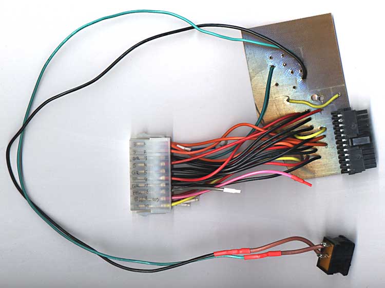
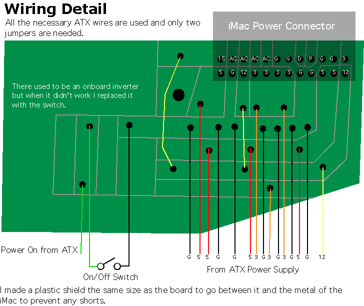
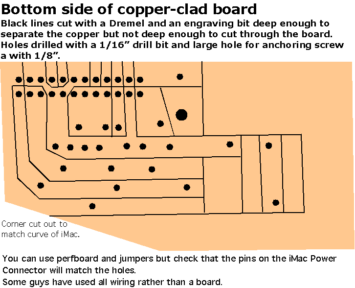
The second and third pictures are the new power board and all the connectors and the PSU switch. It doesn't have Soft Power, maybe in the future I'll make up a little Inverter, see Soft Power below. For now it works. Flipping the rocker switch grounds the Power On line on the power supply. Then I pushed the power button on the front of the iMac. On the bottom of the power board you can see the lines where I used a dremel to cut out the channels. Chemical free. Got the idea from http://www.cryogenius.com/hardware/imac/
Specifically this page: http://www.cryogenius.com/hardware/pcb/
I had a hard time trying to desolder the iMac connector from the original power board, I ended up using side-cutters to 'chew' it out. Then I carefully desoldered any remaining solder and straightened the pins. To get it into the new holes in the circuit board I used a pair of tweezers to move individual pins until it slipped in. Once in place I soldered each of the pins to their new lines.
Then I soldered the wires from the ATX extender to the appropriate line using this site as a guide:
http://www.ct-scan.com/iMacATX/ using a board similar to: http://www.cryogenius.com/hardware/imac/
Here are a couple diagrams of the new powerboard.
NOT FOUND: 4
NOT FOUND: 5
Soft Power
To utilize Soft Power you need to have the Power On (line 14) and Ground (lines 3, 5, 7, 13, 15, 16 or 17) from the ATX power supply and the PFW (line 10) and +5VSB (line 6) from the iMac Video connector.
There are several ways to make the soft power circuit. Some use ICs and the some use Transistors.
IC - http://www.hardmac.com/articles/39/page2
IC - http://www.xlr8yourmac.com/systems/MacinPC_ATX_case/index.htm
Transistor - http://www.radiomods.co.nz/imactoatxconversion/
Transistor - http://www.cryogenius.com/hardware/imac/
IC & Transistors - http://www.webdrive.jp/mac/iMIU03e.htm
iMac Pinouts - Power, video, IDE
Also a link to a manufacturer that sells the connector ($1.04 US) for the power board if you don't want to desolder it.
http://www.hardmac.com/articles/39/page3
iMac Sites
Rev A & B 233-266 mHz iMac with Soft-Power start up
http://www.radiomods.co.nz/imactoatxconversion/
iMacDV 600 in a VCR case
http://www.macmod.com/content/view/192/2/
Discharging a CRT monitor properly (to prevent serious injury or death)
http://www.macmod.com/content/view/232/2/
iMac revival in French
http://pascal.monte.free.fr/imac
iMac 2000 Disassembly
http://www.r3uk.co.uk/content/view/45/61/
iMac Rev A Disassembly
http://www.r3uk.co.uk/content/view/47/61/
Resurrecting a Revision A 233 iMac (sometimes not available)
http://www.carnforth.co.uk/imac/index.php
Fairly comprehensive iMac conversion (different video connections)
http://www.ct-scan.com/iMacATX/
Would that power converter work with a tray loading iMac too?
It should work with any G3 iMac, tray loading or slot loading. I got the set-up from several of the sites listed on this page.
With the tray loaders, soft power can easily be implemented (the conversion here uses a switch).
If I remember correctly, the iMac psu sends a high signal to the psu, while the atx psu expects a low to turn on - hence one npn transistor and a resistor is all that is needed to correct this.
I should of clarified, CRT iMacs not LCD iMacs.
I spent a couple months checking the sites listed on this page (and many more), looking at their printouts, to see what would work for me.
congrats on doing such a hard task. i was about to try that mod but gave up.
I dont believe there was a G3 LCD iMac.
True, and the procedure for a trayloader will be different than for a slotloader. They have entirely different layouts and boards.
Just as an aside, I wonder if it'd be worthwhile taking a poll of people who've done iMac-ATX conversions to see what inverter designs work most reliably. I tried the transistor+2 resistors circuit and found it to be terribly "twitchy" with most ATX supplies. (It worked fine with an expensive PSU out of a server case, but with most others it had a bad habit of flicking back on again after a shutdown.)
--Peace
Your base resistor was probally too high a value, meaning the transistor was not fully at saturation. The transistor probally drifted from fully on, to somewhere inbetween.
1. I researched iMac conversion web sites, printed some out and picked the ones that suited the machine I have.
2. Dismantled said machine and discharged the CRT before trashing it and the analogue board.
3. Bought ATX power supply cable extender, copper clad board, resistors & transistor and VGA connector. I scrounged an ATX power supply from an older computer.
4. Removed male power connector from iMac power down board. Disconnected video cable from iMac.
5. Drew circuit layout for power converter & inverter onto copper clad board. Used Dremel and engraving bit to cut lines and drilled holes for wires. Soldered wires and connector to copper clad board. Soldered resistors and transistor for the Soft Power On inverter.
6. Soldered new VGA connector to old video cable.
7. Plugged everything in and pushed iMac power button. Nothing. Remembering that grounding the power on line on the ATX power supply will start it, I put a rocker switch between the two and it worked.
8. Had to change the video cable, I was getting some ghosting/colour shifting on some text. The cable port photos on one French site looked very much like SCSI cables so I cut one down to match but it didn't have an alignment tab. The iRack had a cable that reminded me of a Mac internal floppy cable, and it matched. Soldered the VGA connector to it and the video is clear. Even with a 4 ft. monitor cable.
The values on the resistors varied from site to site. One man used trimmer pots, 1k* & 50K. (*I think)
My attempt.. I just wired up my 400 DV and as I was soldering the wires in for the power supply I knocked off the cap on the back of the board between pins 6 and 8 ( +5v and the ground ) anyone know what I should replace it with..
I have my speaker harness attached but no video cable.. and when I apply power I get no tones, but i get the main yellow power light on, and it looks like its flickering between green and yellow..
Any Ideas???
The cap from 5V to ground could be a decoupling capacitor. Sometimes you see an electrolytic to short low frequency noise to ground and a small ceramic type cap for high freq noise.
It will probally work fine without it, otherwise just replace it with the kind you knocked off. The value should not matter that much.
but the cap is gone.. and i don't know if ist a ceramic or electrolytic.. more info please..
Its up and running... The soft power worked using a 4069 inverter from the data on the french conversion.. The mac goes to sleep but HD/Fans and powersupply don't... I will try the transister method..
Also I have a 12.9 IBM drive from another DV, but mine only sees the drive as a 2 gig drive.. I have changeds the jumpers but it only sees the drive as a 2 gig drive.. The bios is 4.1.9f1 any ideas??
When I put this drive in my G4 it sees it as 13 gigs like its suppost to..
Abysmal
hey, i have mostly everything finished. I got the power supply conversion done, i have all the essentials needed to make the video conversion.
However i dont quite understand everything on how to get it to power on. I tried a small dell power suppply but it didn't have a power switch so i thought maybe that was the problem. I bought a 350W Power supply that does have a power switch but it didnt power on either. I dont understand the conversion; any assistance would be apreciated. My email is DevilRocks15@yahoo.com or my aim Screen name is DevilRocks16 .
thanks
-Thomas Johnson
You may have problems getting the psu fan to power down in sleep, as the softpower mod only uses the power signal line of the atx power supply, which simply turns the power supply off or on. There are different sense lines which tell the psu when the computer is asleep, but I'm not sure what the signal is.
I'm surprised the hard drive doesn't turn off though, I'm sure mine used to - I thought the computer sent a signal through the IDE cable to tell it to spin down.
I found this take apart photo set on Flickr, it shows a similar iMac and he shows the power inverter board connected and removed.
http://flickr.com/photos/macpolen/sets/72157603976557100/
David