This just a collection of ideas and mostly untested PCB partly even unfinished PCB projects but may it is of interest for someone.
I some one is interested in the design files they are here but be warned it might not work at all: https://oshwlab.com/szillat/PROM-Adapter_copy_copy
There are some more files that might be of interest: https://oshwlab.com/szillat/2519-fixed-smd
RAM ROM board unfinished: https://oshwlab.com/szillat/32-KB-SRAM-Apple-I
The designs are surely not the best it was just done to keep some ideas preserved.
Not all make sense if you want to use modern SRAM and EEPROM don't use a Woz design like board simply use any replica that usees SRAM and EEPROM out of the box and don't have all the issues the the Woz design like boards have.
This are just my first trials with easy EDA.
The traces are often to close or to thin.
The layouts are unoptimized.
I just posted them because of the idea of a dual purpose adapter and the smaler formfactor.
Sometimes you can find EPROMs like this: https://www.ebay.de/itm/185758861305 they look very retro even in PLCC.
If the ACI design would not be so strange one adapter would be enough to hold the content of both.
But as the PROM content on the ACI is used to read 0 and 1 from tape you can not place it in a bigger ROM on the Apple I PCB.
I had the idea to port the tape interface including the beeper from the Apple II to the Apple I.
If I get it right in the Wozanium Pack https://theromexchange.com/documentation/romx/Woznium%20Pack%20Manual.pdf https://www.willegal.net/appleii/brainboard.htm (Apple I Emu for Apple II) is somewhere an ACI ROM that uses the Apple II Tape Port.
Some people build the 2513 and 2519 adapter and got them working mostly they used the schematics and build the PCB them self.
Here is the DIL version of the 2519 adapter: https://oshwlab.com/szillat/2519-fixed
One more https://oshwlab.com/szillat/mc6821-arduino-nano that is partly working it adds a serial over USB Port like in a replica.
It is borrowed from here: https://github.com/DutchMaker/Apple-1-MiniIt connects the nano from this clone to the woz style boards unfortuneately there is a bit of conflict with the keyboard and video section if I rember right as no measures are taken to prevent the conflict.
One connecten DA or RDA needs to be disconnected can't remeber which one it was. Also strobe should have at least an OR in between.
Some idea to work around a not completely working video section (e.g. 2504/2513/2519 missing):
The timing section of the video part needs to be working because it also generates CPU clock and DRAM refresh.
Both could be circumvented if an 1 Mhz oszilator is added to the RAM ROM PCB in that case the video section could be left unpopulated as well as the DRAM section.
But if you do so, you are only missing the VIA and you got your replica 1 complete.
Actually it's not a good idea to use a Woz PCB to build something like a replica I because the Apple I mainboard is far from an optimal design the old parts (drivers) could compensate the very long PCB traces better than modern parts as often mentioned there are ringing isses and if you leave traces open it will make it only worse.http://retro.hansotten.nl/uploads/apple1/r1sch.pdf
http://retro.hansotten.nl/uploads/apple1/replica%201%20firmware.zip
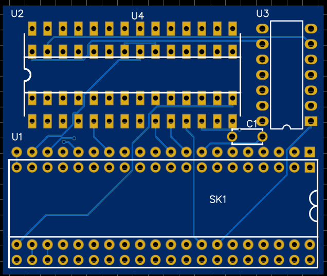
Take a part of the replica and connect it to the real thing:
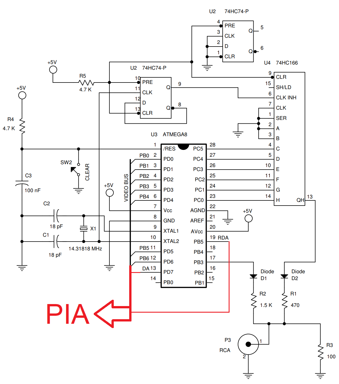
The lines end in the red arrow pointing to via need to be connected to the via so this circuit is best places on a PC between socket and VIA.
two aditional connections are needed DA (PB7) and RDA (CB1) vor both it would be a good idea to put in a jumper that lets you select between connection VIA to this PC o to main PCB.
For reference the part of the Apple I schematics where this needs to connect to:
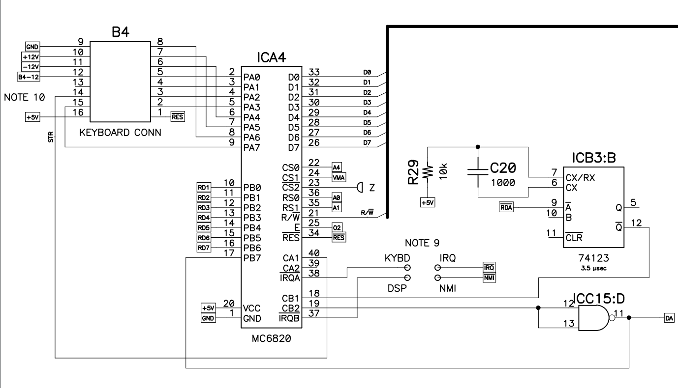
link to full schematics: http://retro.hansotten.nl/uploads/apple1/a1%20circuit.pdf
I had some idea to replace all 7 2504 with one chip:
Here are the two candidates:
1:https://pdf1.alldatasheet.com/datasheet-pdf/view/70979/LODEV/LF9502JC25.html
https://www.alibaba.com/product-detail/-Electronic-Components-LF9502JC25_1600596792328.html
2:
https://www.renesas.com/us/en/document/dst/720072017202-datasheet
www.aliexpress.com/w/wholesale-idt7202.html
both parts are also obsolete but usally easier to get than the 2504
The first is actually twices as large as needed and has 2 unused bits but it can the lenght can be programmed and the 2k version is easier to get than the 1k.
The second chip is of the correct size but the way it is intended to be used is different we want to fill it up to 100% and feed to output into to input (recirculate) and alternative inject new characters.
This might work if the /XI (extend input) is connected to the own /XO (extend output).
It would not make really sense to use this chips on a Woz style PCB but they would allow to create a new PCB with out 2504 and uses simple 2513 and 2519 replacements if you use 5V DRAM the whole board would be 5V.
The video generation circuit would be almost original as no MCU or programable logic is used.
Yes, this board would not look very original but you could iron out a lot quirks and add the ACI onboard and give the board 3 expansion slots to allow a couple of the newly developed expansion boards.
It would be much closer to the original than the clone boards that use one or even two MCUs or remove the terminal completly and just offer a serial interface.
And who is a real Apple fan thinks what is better than one Apple I (clone) board? Two or more Apple I clone boards.
The only Apple hardware I have is an old CRT iMac that that came with the keyboard I actually wanted to have as I liked the design. The iMac was tested, overclocked and than put away if someone is interest it just collects dust. It's a german version.
The Apple-1 has three types of long obsolete Signetics ICs, the 2504, the 2513, and the 2519. These have been unwanted, and worthless, for 40 years. Even back in 1975, when Woz designed the Apple-1, these have been obsolete, unwanted (because of weird supply voltages and clock voltage levels) and hence, cheap. This is why Woz used them. He could buy them for cheap.
Then, decades later, the Apple-1 clone building scene started to take off. IC brokers sitting on stockpiles of these formerly worthless ICs noticed increasing demand and started to gouge prices. Now the prices have reached usurious levels. For instance:
2504 could be had for below $2 a piece. Now they cost $18 a piece. 7 are required per Apple-1 (ouch !).
2513 could be had for $7. Now they cost $200 (ouch !)
2519 could be had for $5. After Mike Willegal brought out his Apple-1 PCBs, prices started to climb. In 2018 you still could get them for $17-$20. Now the usurers want $65 plus shipping.
So I understand why individuals like nats666 try to find substitutes and make these small PCBs with replacement ICs.
But keep in mind the following:
1. The replacements look wrong. Any idiot can see it's not quite right.
2. The drop-in replacement for the 2504 called AM2508 is used in U.S. missile systems and also in civilian avionics and will be available as long as the USA exists and those private jets need to be maintained. From time to time overaged surplus ICs from the military stockpile reach IC brokers and you can buy them for cheap. If you buy 1000+ or so. So, join forces and buy them up, and then distribute them. Rochester Electronics can make new wafers with them, just ask.
3. The 2513 can be replaced by the General Instrument / Microchip Technology part RO-3-2513 CGR001 and there are 10's of thousands available at IC brokers. It's a drop-in replacement. Beware to get the right CGR code (001). All other CGR codes have a different character set which is useless for the Apple-1. Same issue, btw, as with the Signetics 2513: you need to get the CM2140 version. This is very confusing, and many brokers don't know that the "2513" or "RO-3-2513" is just the generic character generator ROM master device number, which then is mask programmed with the desired character set, designated as CM code or CGR code. To avoid such confusion, Signetics stamped the 2513 CM2140 as only "CM2140" beginning with year 1978. This is our chance to find them cheaper than $200 each.
4. The 2519 is the only Signetics IC in the Apple-1 for which there is no 2nd source substitute. Manoshewitz Electronics in Jerusalem sits on 5000+ of them (2519N, date code 1977 and up). So there are enough for 200+ years of Apple-1 building. The only problem is: the usurious price. Best solution would be to boycott them and write nasty letters to them until they reduce the price back to the $17-$20 which it once was. ALL the 2519N you have ever seen in Apple-1 clones come from this source, the only one left in the world. The 2519B in my famous IC kits also came from Israel, but at a fair price, from another source, which now has none left as they forced me to buy all of them they had.
Draw your own conclusions. I think it's not the right way to modify the Apple-1 motherboard to take substitutes. If you want something cheap and affordable with no price gougers / usurers, go for the Apple-1 Replica by Vince Briel.
- Uncle Bernie
This replacements can be used for testing or till an good offer for the real thing appears or as a starting point for a 5V only version that indeed looks different but not all people need it to be bipolar chips I think many would be happy if it has the same formfactor and uses TTL Chips to produce video instead of a Atmel or Propeller and would be happy about integrated ACI and additional slots and accept that 4bit DRAM Chips with only 5V are used to make room for the slots.
Sure this would be neither an Apple I nor an Apple II but your color video card and floppy controller points the same direction that give the Apple I access to Apple II features and that is exactly that what Apple I users would have done that times, but most upgraded to Apple II and the Steves encoraged to do so for different resons, Jobs for profit, Woz because of all the new features he wants everyone to have.
So I would like a new Apple I mainboard with additional feature that directly implement some of the great newly created additions.
If there is enough ROM space one EEPROM can server as Wozmon, ACI, and ROM for serveral extensions.
I am aware that not everyone shares my opinion.
As said before get one Apple I mainboard looking as close to original as possible, for me every chip could be broken, as long a it looks good. Get a second one for fun to play and develop with extra features and comfort.
If you think even broader you can imagine an Apple I/II hybrid PCB that can be close to 100% compatible to both.
Personally, I think any alternative to the original chips is welcome, even if only for testing or troubleshooting or temporary unavailability of the 'original' components.
Or just because "it can be done", or become a way to learn something new.
I also find it extremely appreciable that natas666 makes his projects available to everyone, and for that I greatly thank him.
Great job! :-)
First of all this is not usury. Usury is lending money at a very high interest rate. What you are describing is cornering the market and the way to combat it is through alternatives like the ones offered in this topic.
The idea of writing nasty letters is absolutely ridiculous. If you follow that logic, then people should also start writing nasty letters to you, since you bought all the affordable chips from the other company and now it’s only possible to buy them thought your kit. That would be equally ridiculous.
Aside from the ACI code, this is exactly what the Replica-1 Plus does (I am saying this informationaly, not to discourage you).
In regards to a board that can do both Apple 1 and II functions, you might find Mike Willegals "brain board" or at least it's source code interesting, as the board allows running Apple 1 code (and a custom ROM) on an Apple II including via the cassette interface. I have made several of these myself.
This designes above have been created to help some users from a German Retro Forum64 to build there Apple I Clone. As the name implies the main target is Commodore C64.
Maybe sometime I will build an Apple I 5V only board that uses TTL for video generation maybe even VGA.
I already had a clother look to this project: http://debuginnovations.com/TTL_Terminal/home.html
If I remove the PS2 and serial controller PIC16F18857 it is actually a modern version of the Don Lancaster Circuit Woz used.
As this design is RAM only it gets preloaded (charmap) from the PIC, so I would exchange the Char RAMs with Char ROMs, doing so I would loose some features but I don't need them all.
I also would like to have some kind of front panel like this project: https://hackaday.com/2018/06/13/vcf-east-cactus-retro-because-it-wants-to-be/
As there is not much Apple I software and the existing software only uses some littel bits of WOZMON I would not care to much about compatibility.As the only Apple I chipset IC the VIA is seldom directly used.
Most of the software should work on compareable 6502 machines and if not it can be ported with only little mods.
I am the oposite of an apple fan, I like that Woz got that thing working and how creative he solved some problems.
I am born 1975 and was interested in computers before I was able to read.
The my time started with ZX(19)81 and than Commodore 64, I cannot remember anyone using an expensive Apple machine that could do basically the same things and that not even much better. Beside the mobile devices Apple is still quite uncommen in Germany and I am happy about that, as I absolutly do not like there politics.
So for me it would be nice if I can reconfigure it to a MOS KIM by changing some PCBs or some flexible design.Or some other device I missed by my age, like the Super Jolt, SYM-1 or AIM65.
I like how the MFA Computer is build: https://de.wikipedia.org/wiki/Mikrocomputer_f%C3%BCr_Ausbildung
Or the RC2014 https://rc2014.co.uk/ with propper CPU board: http://ancientcomputing.blogspot.com/2017/05/a-6502-cpu-for-rc2014-part-1.html
In post #5:
"The idea of writing nasty letters is absolutely ridiculous."
Uncle Bernie disagrees.
We have the special situation that ONE sole vendor has ALL the parts of the wanted type on the whole planet. A monopoly. And he asks usurious prices (although we could argue about the proper word for that forever).
The only way to bring them (Manoshevitz) back to earth (pricewise) is to BOYCOTT them. Anyone who buys one of their $65 + $12.50 Shipping 2519N off Ebay undermines the boycott. And now, assume the Apple-1 builder community boycotts them, and they sell NONE anymore, they will need a nudge by "nasty" letters (or email, or Ebay message) telling them why they can't sell them: "look, your prices are unacceptable, but if you sell me X pieces at Y US$ (or Shekels) we may have a deal". This is what I meant with "nasty letters". Not childish death threats or calling them names. But you have to contact them, point out their prices are unacceptable, and make an offer. If you have ever dealt with that Tribe (or other Semites like Arabs in general) you must understand that their culture to do business is to first quote absolutely ridicolous prices, far, far higher than what the merchandise is worth. And then the bargaining / haggle over the price starts. Which can get very temperamental, with insults etc. (beware only some specific words depending on the locality are allowed for these insults). The whole act is augmented by hand waving and gesticulating and pretending to walk away, it's like a comedy. But it's part of the game. And, if everything goes as it should, a deal should be struck at a price where both parties can live with. And then comes along the bloody tourist and pays the full, ridicolous, stratospheric price. And the vendor can close shop for the rest of the week because he has made a weeks' worth of profit. From that bloody tourist.
I agree that the substitutes by natash666 (and others) can help to make a boycott possible. I would like to see a more "invisible" solution, though. On the solder side of the motherboard. But modifying the motherboard as such IMHO is not the proper way. The creators of these PCBs have invested a lot of time and effort into making them as accurate as possible, why desecrate their work with irreversible mods.
Oh, and about the other vendor - I did not want to buy their whole stock of 2519B. I only wanted to buy one tube of 25 to complete my last kits. But they were not interested to sell me one tube. They said: you can have them but you have to buy all of our stock, at once. It took me more than one year to sell off the excess - and I sold them off at the same price I paid for them. Not one by one, not worth my time. They went to builders all around the world, tube by tube. I made zero profit from that. But I could complete the last kits.
This nasty policy of "you have to take all of our stock or none" is quite common among IC brokers which sit on otherwise unwanted ICs. This is why I still have 300+ of these UA323K regulators in my basement. Just to get the 30 or so I really needed. Still, it was less expense than paying the $65.62 a piece Mouser wants at qty 10. Even if I throw the 300 superflous ones into the trash, at a total loss, I win. (Don't ask me to sell you one of them, not worth my time. If you want to buy 100 of them, minimum, send me a PM.)
- Uncle Bernie
Yes, in the wozaniam pack code with the Brain Board it allows use of the Apple II tape port for Apple I audio programs.
I have a RC2014 Pro Z80, one of my favorite little machines. I have pondered the idea of building a 6502 one, but I already have a DB6502 (PCB based on the Ben Eater 6502 projects).
@UncleBernie the substitutes just plug into the socket. There was never the idea to hide something. Using SMD it should be possible to make versions that hide an SRAM or Flash chip on the backside or in a socket below a chip.
If someone asks for something like that i would be glad to help to modify it in a way.
How would you do that fully isolate the PROM sockets o snip off all leg beside two to hold the so let in place? so what ever you plugin gets ignored while the real ROM is below the CPU?
Bild_2023-03-24_220824827.png
Some thing like that on the picture should would be an idea.This is an adapter to fit an SOIC28 IC in a DIP 28 socket.
Move the vias to the other end of the solder pads and cut a rectengular hole a little larger than the inner IC silkscreen shown on first picture.
Exchange top and bottem layer and immerge chip flipped over in the rectengular hole.
Enlarge the drill holes a 1/10 of an mm and cut the borders as shown in second picture.
Place that PCB on the solderside between the legs of the DIP IC and solder it like the ESP32 modules.
I am not sure if there is enough room for all the traces as this should just explain the idea.
What would be needed is an adapter from 6502 to 28c64 only a little part would be used (virtual 28c08 A0-A7, A8-A12 tied to fixed level) and one bodge wire would be needed that connects the /OE to Y (/CSF).
This business card shows the idea: https://hackaday.com/2010/05/25/mass-storage-business-card/
You boycott by simply not buying something that you deem too expensive. We all do this every single day multiple times. Writing to them about it would be just a waste of time and it will achieve absolutely nothing. If they already sold 45 of them at that price since the listing started, they are happy with it and will not change it just because someone finds it too expensive.
Besides they are not the only ones that have these chips. You can always find them cheaper somewhere else, like here.
I think two Logic Devices LF9502JC-25 can replace all 7x 2504 at once and the 2519 as well.
Alternative Part No. Harries/Intersil/Renesas HSP9501JC-32
The two just need to be configured for a different length.
Problem is this needs to connect to ICC3 ICC4 ICC13 and ICC14.
The DS0025 would be also needed to be replaced with a Dummy.
https://aliexpress.com/i/4001024909076.html
In post #10, natas666 wrote:
"How would you do that fully isolate the PROM sockets o snip off all leg beside two to hold the so let in place? so what ever you plugin gets ignored while the real ROM is below the CPU?"
Uncle Bernie answers:
I thought quite a lot about substitutes as the number of kits I can make is limited (only a dozen left right now).
I think it's important to keep the "looks" - unless the substitutes are meant just to check out the build.
So every substitute meant to be permanent - and preserve the "looks" must be moved to the (normally invisible) solder side of the motherboard.
In case of the PROMs, you could make a small PCB with a SMD EPROM, as you have mentioned. This could fit, as you say, between the pin rows of the 6502, where all the required signals are available. You could put a 32kx8 or 64kx8 SMD SRAM in the same small PCB. And then disable the 8T97 bus drivers to make the Apple-1 ignore the DRAM. Just sayin'.
This leaves the question what to put into the now empty PROM sockets for the "right" looks - just put any used bipolar PROM of the 256x4 or 512x4 type into these sockets and disconnect one /CS line - i.e. the one below A1, cut the little stem which goes from the long trace to to pin #14. Now the /CS on both A1 and A2 PROMs float high and they are inactive. But look as if they contain the Wozmon. Hehehe. No so. Just an illusion. But the Apple-1 would work. You could even use the whole 4k and add a more sophisticated monitor program (but leave the upper page with the Wozmon intact - we owe that to Woz.) If you don't like cutting traces, just snip the lead on the pins#14 of both PROMs in A1, A2 such that they don't contact the socket.
So we now have solved the PROM and DRAM problem (if it's real).
For the 2504 and 2519 sockets, it should be possible to find some DIL-8 or DIL-16 ICs which could be put in there with minimum number of disconnects. I did not go on the quest to find candidates for that - I would have a bag of bad 2519 as "dummies" for that purpose. Then wire in any substitute PCB with flat SMD ICs on the backside. Six CD4557B ICs can substitute the 2519, as other contributors have shown. However, unless you disconnect the -5V from the 7k5 resistor group, these CMOS ICs will die. This would involve cutting one trace. You could also add six small Schottky diodes like 1N5711 to protect the CMOS ICs from negative voltages (PN junction diodes won't offer the protection) to avoid cutting that one trace.
Replacement of the six 2504 would be possible with 2 x 2114 type 1k x 4 SRAMs and a counter. But since these are clocked only very slowly in the Apple-1, it may be possible to use a modern, fast microcontroller to do this per software. And replace the 2519 at the same time.
Yet another possibility is to just replace the whole Apple-1 "terminal section" with a small SMD FPGA that lives on a PCB strip between the PIA pin rows. The tricky part here is to find an FPGA which would tolerate the +5V environment, but if you are willing to put small 0805 SMD resistors as voltage dividers in, at all the 10 inputs you need, you could use a 3.3V FPGA, which are more easy to procure. Even if you would use a modern FPGA with just 2.5V I/O and a lower core voltage, this would work.
The best mechanical solution for these "between the pin rows" PCB strips would be to make them with pads on their outer edges which could connect to the solder pads of the DIL-40 6502 and 6520 solder side by just a solder blob / solder bridge. To remove the PCB, you just would run a length of solder wick along this row of pads, heat it with a wide enough solder tip, and when all the solder bridges are sucked up, the small PCb would just fall off, without a trace it ever was there.
These are just my thoughts, I did not design or try out any of these substitutes. All I wanted is to share some ideas how the Apple-1 could be built without using any of the "rare" or "too expensive" parts and still keep the looks correct. It's a foul trick, sure, but museums do that all the time if they want to show vintage machines in action but lack "unobtainium" parts. They then make functional replacements and hide them somewhere from sight.
And if you have an Apple-1 using such add-on substitutes, and somebody finds a stash of the "real" ICs, then you can remove the substitutes and put the "real" ICs in. This would not be possible with a motherboard that had massive layout modifications to take substitute ICs.
In any case there is no reason to panic (nor to pay the usurious prices).
Apple-1 forever !
- Uncle Bernie
My proposed solution to keep the video circuit only for CPU clock and DRAM refresh and use an Atmega 8 for the rest (back ported from Replica 1 the oldest version) seems to be a small and cheap solution. As most connection need to be done to the VIA below that chip would obviously a good place.
The 74166 part is already on the Apple I PCB and with little rewiring to the Atmega should be useable.
A fitting crystal is also already there so i see no reason why not get clock from the Apple I Board as well.
If the H/V Sync gets in sync with the Atmega 8 (needs code changes) it might be possible to get the wire count down a couple of more wires as more parts of the Apple I can be used.
If that is a good idea is a different question.
Thinking about your tricks to get the signal a bit more in direction NTSC standard.
Placing a SMD NTSC oscillator and a TQFP Atmega 8 would result in a very small board and would also solve some of your clock problems.
I have an idea as alternative to cutting traces drill out vias let's take the crystal for example if you drill out the via, the part can be soldered from top or bottom side while not having contact to the corresponding trace on the other side.
Unfortunately we already reached the point where selecting a larger MCU allows to emulate the complete Apple I.
Where do you see that any of the pictured not discussed substitutes need any layout changes?
They are designed as plugins to the sockets.
The 2519 just uses the normal empty socket for stability and to get 5V.
Removing R30-R35 is not a layout change to me.
I don't know if you have seen the 2519 replacement using dip Chips if you order der PCB without solder mask and make the traces look like hand drawn it looks like a self made PCB or simply use a hole matrix board and hand wire that looks old school enough.
Bild_2023-03-25_181006958.png
Bild_2023-03-25_181119084.png
It offers 8K ROM from $E000-$FFFF. The Replica I ROM should work out of the box it places Integer Basic at $E000-$EFFF , Kusadar at $F000-FEFF and Woz Mon from $FF00-$FFFF.
https://oshwlab.com/szillat/32-KB-SRAM-Apple-I_copy
What do you think does a solder jumper to disable it make sense? So you can leave it soldered when testing some PROMs?I do not like the bulky tripple input nand ic that is only used to 1/3 would would the old school guys use? 3 diodes a transistor and a resistor?
To build that in easyEDA was for me actually the fastes way to create a sketch to illustrate the idea.
There is even enough space to fit a second Chip in the same TSOP case so it might be possible to fit 32K SRAM on this board aswell.
For address decoding it should be enough to wire A15 to /OE and /CSWith one of the two unused NAND ist should be possible to invert R/W and with that last one combine it with PHI2.
https://www.mouser.de/datasheet/2/698/REN_71256SA_DST_20200629-1996300.pdf
As I do not have experience with PCB layout I do not think I will fit both on a 2 layer PCB and would likely end up in a 4 layer.
There should be an pull-up on /WE to allow to solder an empty EEPROM and use an Programminga adapter.
It should be even possible to use the Apple I as Programmer but some switches an PROMs would be needed.
The problem is if a boycott isn't done by every buyer then the seller may keep selling and not care about selling a higher quantity at lower price. I see nothing wrong with writing a seller to convey thoughts about pricing which may influence their futuring pricing. They may have sold 45 at lower prices before increasing their price.
The link you provided seems to be not a legitimate site. If you do a search for the website name it has a low trust index and the contact us page just links back to the sign up page. The picture of the 2519 chip is from a blog website about a road trip to silicon valley and building an Apple 1 some years back.
Justin
This is a very good idea. I'm interested in this if you can design it to fit in a small enough area.
Justin.
Organized boycotts don't work precisely because it's impossible to get everyone to do it. What is expensive for one person might be very cheap for another. Besides these guys have over 1000 other items in their eBay store and they wouldn’t care about this one chip. Not only that, but they are not the only listing on eBay at that price.
It's quite possible. Lots of unscrupulous people out there and when you try to get something below its market price you always run into risks.
And maybe these chips are really worth $65 if they are so hard to find. If an original Apple I has about 50 chips and sells for $500,000 - who is to say that every one of those original chips should not cost more than $20 today?
This is why you only get to decide if something is too expensive for yourself and not for everyone in the world.
In Post #18, CVT wrote:
"And maybe these chips are really worth $65 if they are so hard to find. If an original Apple I has about 50 chips and sells for $500,000 - who is to say that every one of those original chips should not cost more than $20 today?"
Uncle Bernie comments:
Over the past 3 years, I have sold lots of Signetics 2504, 2513 and 2519 with Y1976 date codes to owners of originals worldwide. Some opted to buy several sets so their heirs could keep running these original Apple-1 forever. And I sold all these "rare" IC at my own cost, no profit. A 2519B with date code 7627 does not suddenly become worth $1000, or $10000, ... if it is plugged into an original Apple-1. Much like that $15 light bulb you can buy at Auto Parts does not turn into a $1500 light bulb when you plug it into a Lamborghini Miura instead of a Toyota Corolla.
All my recent kits have such an original Signetics 2519B with date code 7627 inside. Should I charge $1000 more for the kit because of this fact ?
And about the price of the 2519N Manoshewitz charges - I am angry at them because ALL the 2519N I ever had I bought from them, and I got them for $17 ... $20 at qty 50 (two tubes), and then when you consider there was another US based IC broker as the middleman, who does add his own margin, these parts were reasonably priced. And all of a sudden, the same outfit wants $65 a piece. Even from me. When I told them I would buy more than one, no decrease in price. This is usury and greed. Which forced me to buy ALL the stock from the other vendor in Israel who had the 2519B with the Y1976 date codes. That vendor would not sell smaller quantities, they wanted to get rid of the whole lot they had. And so I had to write a $8000+ check just to get the 50 pcs of 2519 I needed to complete my last kits - and then I had the headache how to recoup the money I had sunk into the whole lot, which was several times the quantity I needed for myself. Took me a year to sell them all and get my money back. This waste of irreplaceable RQLT brought about by the greed of one vendor who I once trusted is what makes me angry. And why I propose a boycott. They should learn the lesson and come to their senses, and start selling them at a more reasonable price. So future Apple-1 builders are happy. And I think at the lower price point they could sell many, many more and actually make more profit than by setting a price point which simply spells G-R-E-E-D. And forces builders to venture into ugly substitutes. How else could they sell the 5000+ of them they are sitting on ? Once everybody uses substitutes it's game over and these parts will never be put to the right use. Which is in an Apple-1 clone. No other use for the 2519 exists anymore.
BTW, I also agree with 'justinmc' (post #16) that the 2519N seen in that dubious website may be a scam - not that I spent the time to find the source of the photo, as 'justinmc' did, but I have noticed that the upper surface of the IC looks black, as in 'black paint', and this is what Chinese counterfeiters do. Now, I can't say if there never have been Signetics 2519 with a black top, as this was a common process if parts had to be re-stamped by the original manufacturer, but the need to do that was rare, so buyer beware !
Unicorn Electronics still lists their 2519N at $49.99, I looked today, and this is the best price for single 2519 I know.
- Uncle Bernie
You are upset at $65, but not at $49.99?? Give me a break!
I also find it very hard to believe that you have not seen something go up in price by a factor of 3 in a very short time, especially recently.
You also have to realize that most of the stores on eBay do this for a living and just because you can sell chips for no profit doesn't mean that they can. Also if they are based in a developed country like Israel where the cost of living is high, their prices will be higher as well. From what you have written it seems more of a personal vendetta and I think you are blaming them for some bad decisions that you have made, but this is just my personal opinion.
Bild_2023-03-26_002603482.png
Bild_2023-03-26_002840125.png
Link: https://oshwlab.com/szillat/32-KB-SRAM-Apple-I_copy
As interesting as the discussion about the sources is I would prefer when my designs would be discussed here.
The easiest solution would be not trying to use the Displaylogic with all the hard to get parts at all.
I could do a PCB like the one in the post above with the DRAM and PROM replacement.
That PCB would be needed to be installed under the 6820/6821.
But it would use an SMD 14.318182 MHz Crystaloszilator and and SMD Atmega 8 and a 74HC166 and would replace the complete Video Generation.
It's basically a back port of the Replica I Video circuit.
That sounds great but the problem might be getting a board small enough without 6 layers since that increases the cost dramatically. I'm looking forward to seeing what you come up with.
Justin.
Actually not, the board for the Video has some strange placement but is only 2 layers:
Bild_2023-03-26_050041309.png
Bild_2023-03-26_050143940.png
https://oshwlab.com/szillat/apple-i-video-replacementThe resistor with the text VIDEO right beside is the actual video output.It might be possible to fiddle in somee programmingpads on the top side. Some insulation tape would be need to cover them after programming.
One connection for clear is also missing.This circuit does not need 2513, 2519, 2504, DS0025 and minimum a hand full of more components will not be used as well.
Actually if both of this PCBs are used there is not much on the main PCB that is used CPU, 6821, 5V voltage regulator and clock devider for CPU clock, Keyboard interface and the connection to expansion connector.
I am quite sure the RAM ROM board is possible in 4 layers.
The problem with that one is there is simply not much space and to nearly identical chips beside each other is the worst configuration possible.
If one is on each side, with some luck even 2 layers could be possible.
The PCB with only EEPROM is 2 layers.
I designed the PCB in a way the parts are visible.
I am not sure if you think same or if you would prefer that it to look like this:
Bild_2023-03-26_162152157.png
There can be no silkscreen or what ever is wanted like 6502 or 6821.As this SMD parts are quite thin it might work to solder them with parts facing Apple Mainboard.
DO NOT TRY THAT WITH THE DESIGNS AS THE ARE RIGHT NOW! BECAUSE TRACES NEED TO BE REROUTED BEFORE!
Especially the RAM ROM Board is quite thick so it will still look strange and for diagnostics hidden components are not very helpful.
I got the design of the 32K RAM 8K ROM replacement down to 2 layers:
BUT it does not fit between the rows of the CPU it is slightly larger than the CPU footprint and I need to remove the caps I placed close to the ICs, I see no change to fit them in.
If any one has adittional ideas please let me know.
The Eprom is by intention in an strange angle to make it fit.
I added this version to the project: https://oshwlab.com/szillat/32-KB-SRAM-Apple-I_copy
Bild_2023-03-26_182706635.png
That design looks great, well done. What about programming for the Atmega, that's based on an older Replica 1?
Justin.
That's good you got the layers down to two and the size is only slightly bigger. Did you try positioning the large chips with one on top and one on the bottom of the board?
Justin.
My opinion would be not hidden because as you say it allows access for diagnostics. If it could be installed in place of the 6502 or 6820 on the top of the board then maybe hidden components with black solder mask and silk screen to look a bit like the chip it replaces.
Justin.
Yes, it's the Atmega 8 from Briels Replica 1 First Edition, (I think second uses same code).
The thirst Edition and newer does not use Atmega it uses an Propeller to substitute the 3(!) Atmels that have been used in the 2nd edition.
You can find the code in the link provided above on Hans Ottens greate page about Apple I Replicas.
I checked if there is an easy way to add an ISP connector but i did not find any.
Yes, I tried every variant I could imagine, guess how I found out that rotating some parts to strange angles can improve the result dramatically.
We can not remove the last two chips?! Okay we can: https://hackaday.io/project/7488-arduino-based-apple-i-emulator
I updated the DIP version with the now hopefully finished schematics:
Bild_2023-03-26_204719435.png
Please note the Resistor colors are wrong in the rendering.
And I did not find out how to get rid of the bridges in the 28 pin DIP socket for the 28C64B
The idea is to place the 32K SRAM below the EEPROM.
Bild_2023-03-26_205026790.png
As I do not have any Apple I PCB I can not test the designs!
The schematics should now be complete. It is still untested and might not work at all!This extension is ment to be pluged into the CPU socket of the Apple I.Measures need to be taken to prevent conflicts with the onboard PROMs and DRAM.IC A1, A2, A9, A10, A11-A18, B11-B18 need to be removed or disabled.In both socket of IC A9 and A10 pin 11 needs to be bridged with pin 12 and pin 13 with pin 14 or extension will not work for sure.
I'm going to guess it was by accident. :)
Justin.
It becomes interesting to determine what is appropriate as an addition to an old computer like the Apple 1 since modern parts can replace the entire board and run it in emulation. Is it still an Apple 1 if an arduino is stuck to it? I like the idea of having hidden electronics with the original form factor but that is more difficult than just adding devices to the board. If I get a chance I'll order some boards based on your designs and see what I can build.
Justin
I would wait till at least someone else than me checked the schematics or better somene build the DIP variant on breadboard.
Bild_2023-03-26_224432553.png
I added 3 Jumper fields:
Both oval pad bridged means normal operation.
The rectengular and the middle pad bridged means programming mode.
For programming you need DIP40 socket with precision pins and an some cable that fits to your ISP programmer.
Bend the pins a little inwards so the clamp the PCB place the socket on the non populated side as silk screen shows.
Most Atmel ISP headers have the following pinout (look from top into holes):
Pin 1 MOSI goes to Pin 24 of the DIP40 socket
Pin 2 Vcc goes to Pin 20 of the DIP 40 socket
Pin 3, 4, 6, 8, 10 GND goes to Pin 1 of the DIP 40 socket
Pin 5 RESET goes to Pin 34 of the DIP 40 socket
Pin 7 SCK goes to Pin 18 of the DIP 40 socket
Pin 9 MISO goes to Pin 22 of the DIP40 socket
After programming and verifying you must change the jumpers to normal operation!
Something else I forgot to explain:
Pin 12 of IC B3 on the Apple I PCB should be bend out of the socket to prevent collisions!
There is one more thing an additional .01µF ceramic disc capacitor might be needed between CB2 and VCC on the 6821. [added]
I am not sure about that that was a bugfix of the Replica I and is likely needed when the Video circuit of the Replica I is used. see details here: http://retro.hansotten.nl/6502-sbc/apple-1/replica-1-briel/first-replica-1/ (Hardware bug)
I guess 3 little components need to be squeezed in somehow: 1x smd NPN-transistor 2N3904 and 1x 4.7K resistors and the cap mentioned above. [added]
On the left you see two "big" pads marked VIDEO the and S and - they are the video out S for Signal and - for GND.
A wire on the pad marked CLR to the keyboard connector pin 12 will enable the CLR key.
Looks good. I wasn't going to rush into anything it might take me awhle to get to it anyway. We'll see who offers comments on the design.
Thanks for doing this.
Justin.
I updated Post #33 https://www.applefritter.com/comment/102204#comment-102204
I added a 1 MHz Osczillator to the through hole version of the 32K SRAM and 8 K EEPROM board.
That should make the CPU part independedn from the terminal part and is mainly use full when you use some replacement for the video terminal part, that can either be the Arduino nano serial interface or the Atmega 8 replacement to be mounted under the 6821.
If build a small PCB with only 6502 socket and 6821 socket and a 5V power connector and a 14 Pin Keyboard connector and use this replacements you have possible one of the smales Apple I compatible boards ever created, the biggest part on this board is most likely the expansion connector.
Why do I place here so much unfinished and even untested stuff?
First I would like to clarify the simple things like the through hole version of 2513, 2519 and PROM replacement have been build by others before and can be considured to be working.
The recently added stuff is indeed untested there are some reasons for that:
I don't have any Apple I hardware (and I do not want to have any).
I just do it to relax and get some other things out of my head.
So why do I post it here anyway?
Because I hope some people here with a very good experience of electronics and even Apple I can have a look to it and point me to possible problems.
And to see if someone is interested in this stuff, if that is the case, see if it meets the needs if not adjust it, debug it and get it running.
As I am sharing the design files any one who is interested can clone them and work on them.
It should even be possible to order the PCB online but before doing so someone else should have a closer look to it to see if there are design problems or errors inside.
This are just my first trials to with PCB design tools so I do not expect much of them.
Yes, the schematics do not look nice and neat as they grow with ideas.
And I just create the PCBs for me to be able to imagine how it would look like and how much space is needed.
Almost all traces are autorouted with no optimisation.
For me it is fun to test some placement ideas and see if it fits.
If some real PCBs are of interest it would make sense to increase trace thickness of power lines and do other optimisations.
E.g. check for traces that are too long or to close or add some GND areas on empty space or even add 2 inner layers for power.
If someone likes my design or just some ideas from it feel free to use them.
Seeing some of them appear in other designs would make me happy.
You don't really need to justify posting stuff like this. I'm glad to see it, even if it is untested. It gives ideas and that's good enough by itseld.
I just want to prevent wrong expectations. Because the renderings look like a more less finished product but they are not.
I just wish to get some more feedback even if people say they don't like it for some reason I would be really happy to hear that.
If someone is interested in any of the projects I would be happy to get the project finished and working.
If the VMA mod is used most of this replacements actually can be placed on an expansion board that connects to the side or top connector.
If that option is more interesting for you let me know.
Bild_2023-04-01_181751361.png
Photo borrowed from W.Sanders https://apple1notes.com/wp-content/uploads/2020/07/Apple-1-VMA-Activation-February-15-2015.pdf
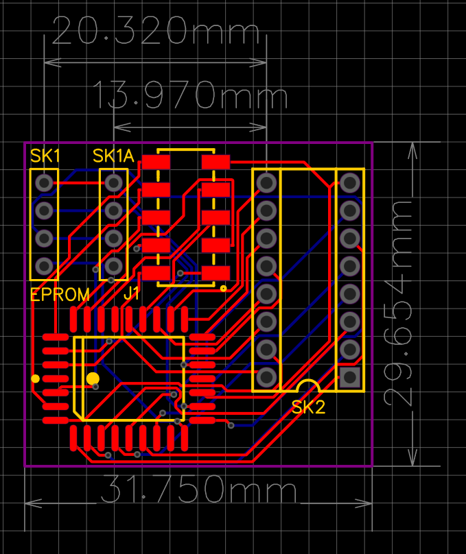
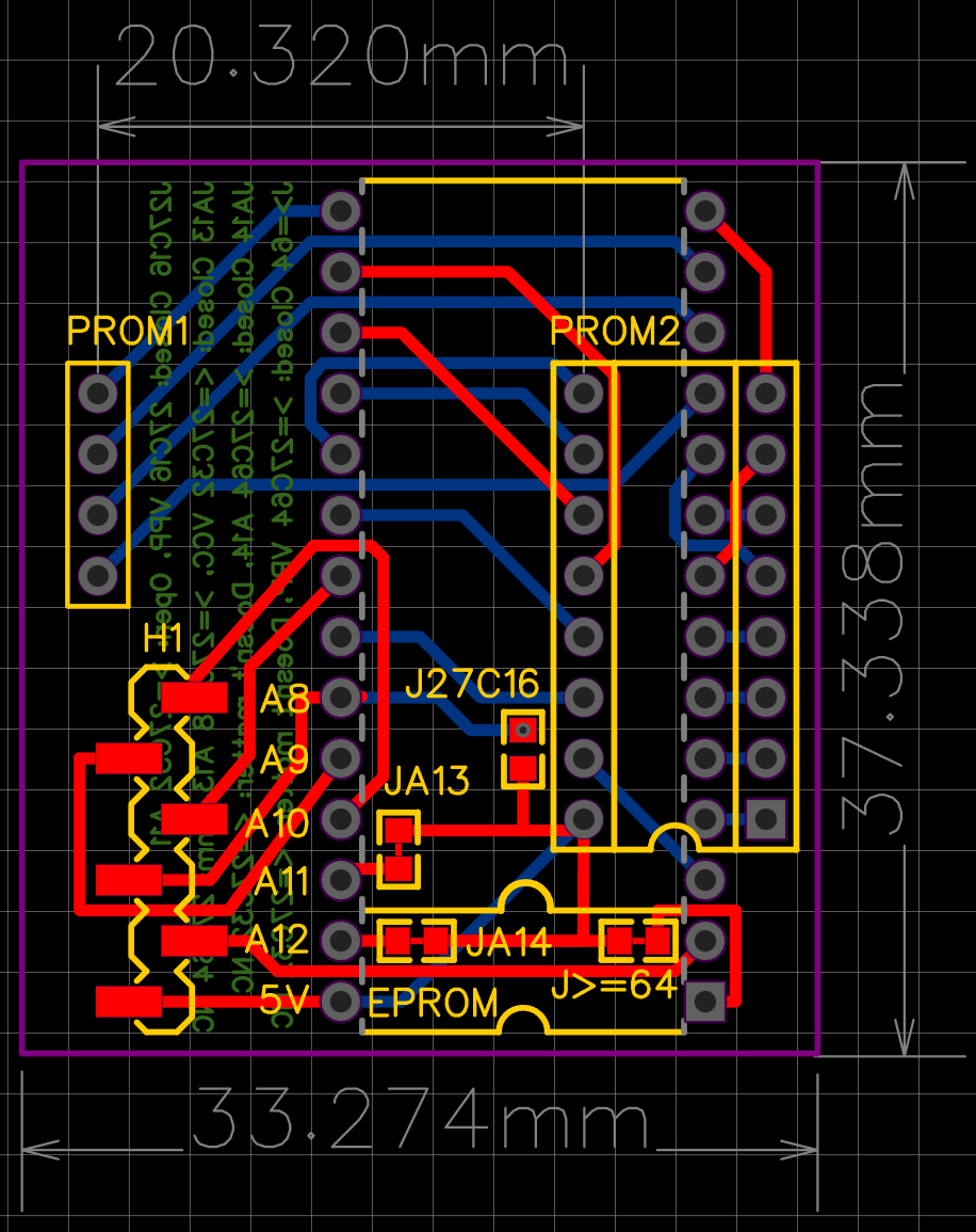
Some note to the PROM adapter from the first post.
It is designed to mechanical fit on the Apple I and on the ACI PCB.
I missed the fact that Woz changed the nibble order of the PROMs while it matches on the Apple I it does not on the ACI.
So to make it work for the ACI you need to swap the nibbles before you burn the file to the EPROM.