Hey all,
I built one of these cards but I am running into an issue where the LM3940 is outputting just over 1.5v, instead of 3.3v. As such the board is not working.
It seems to expect a decoupling cap on the input, and polarized cap on the output. However let's look at the application of this regulator in the design I'm using/building, shown bottom right:
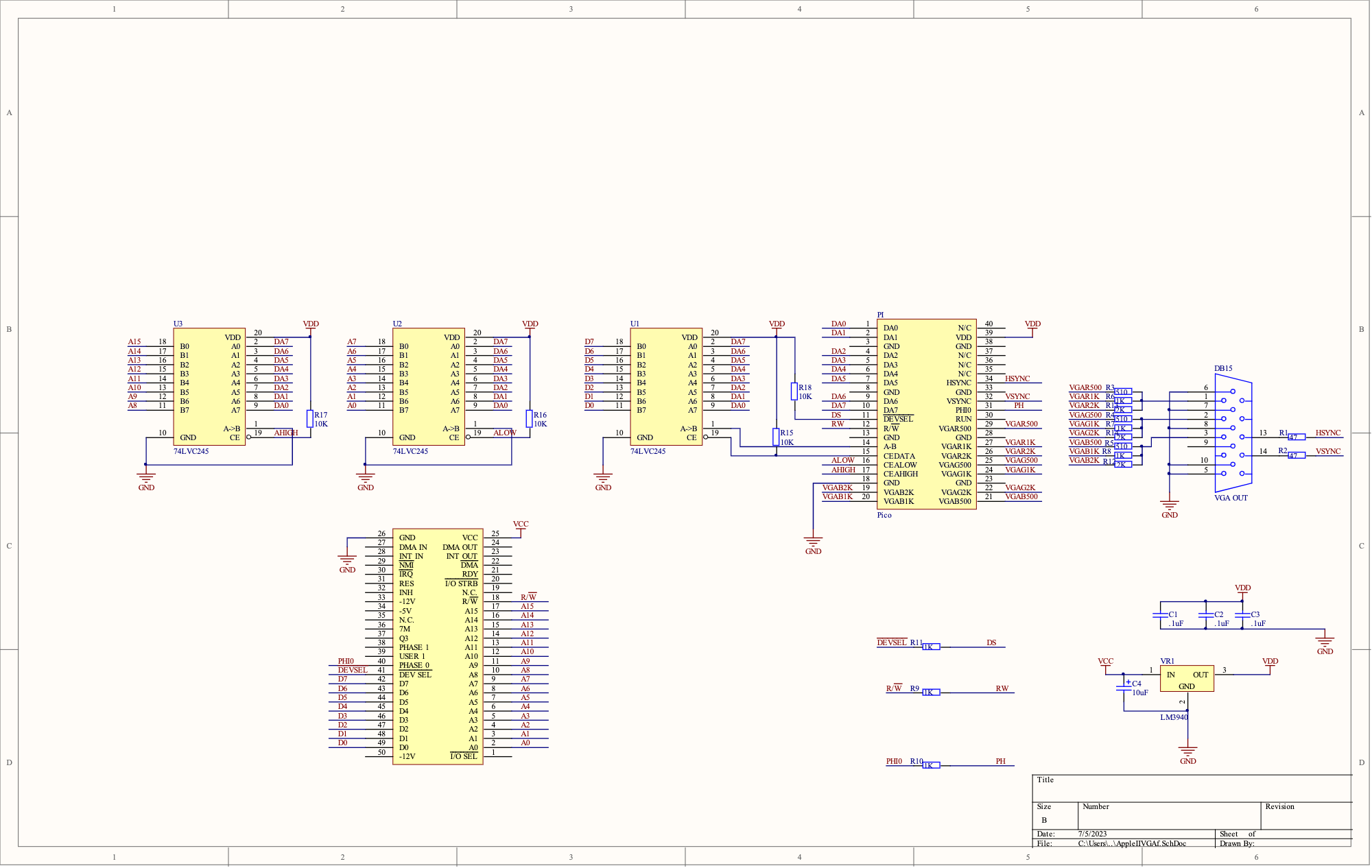
C4 is a polarized 10uf cap on the input, and the output doesn't seem to have a capacitor present.
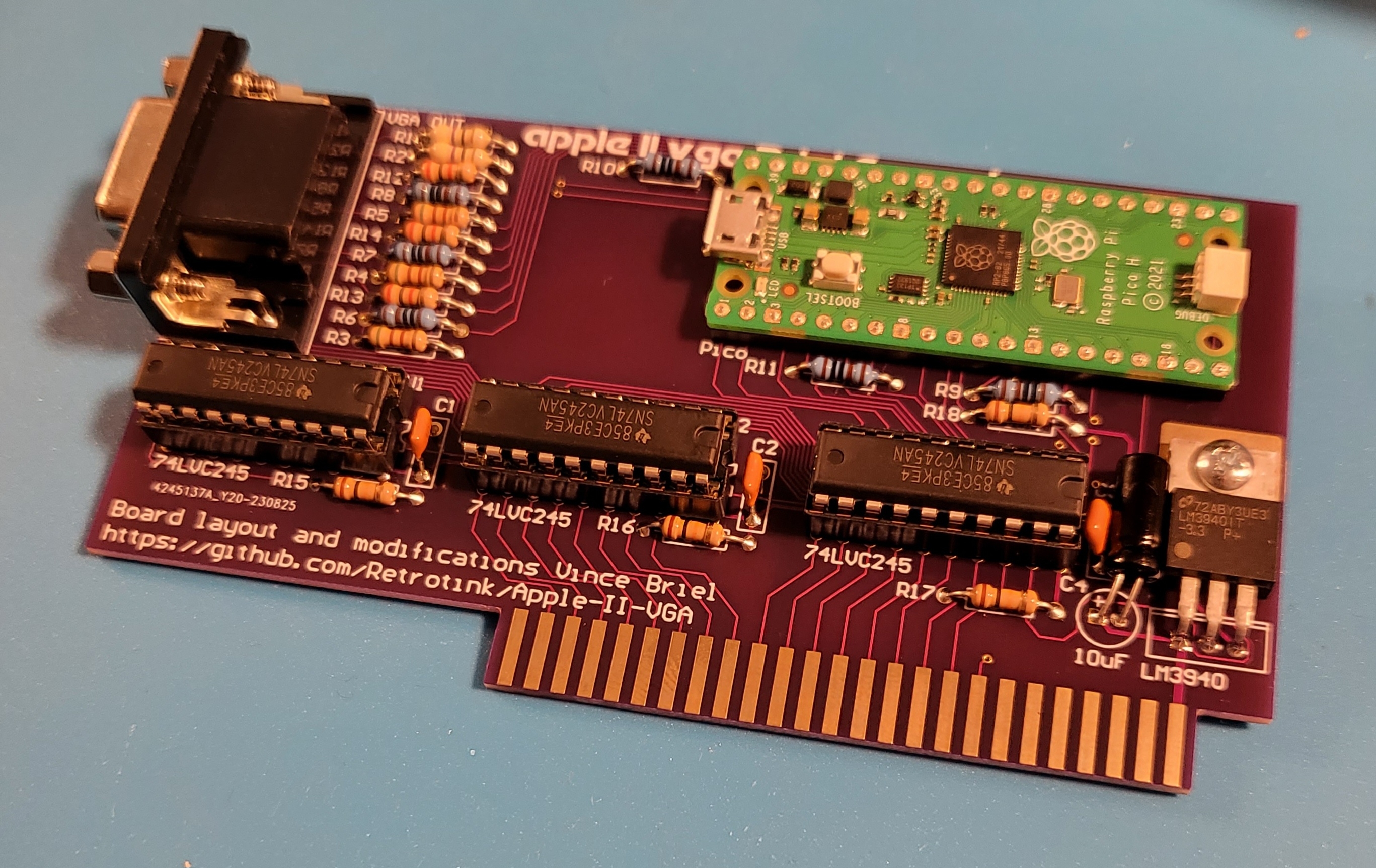
I have already desoldered and replaced both the regulator and capacitor, and with another regulator, I'm getting the exact same voltage.Should I be looking to add a cap to the 3.3v output, a different cap on VCC input, or both? Surely I can't have 2 identically faulty voltage regulators? 5V tests great going into the card. Photo for reference though it should be all but identical to the one on the github for the project https://github.com/retrotink/Apple-II-VGA
Is the Pico socketed? If yes, remote it and remove all the chips to see what happens.
Sadly I did not socket the Pico. I am regretting that right about now. I tried a fresh set of 74LVC245's just in case, but that was before I had measuered the voltage regulator output to know it was reading low. But, no difference regardless. I could try seeing what happens with those 3 sockets empty if there's any reason to.
You should still be able to unsolder the Pico's +3.3V power pin.
Are the two regulators from the same batch? Where were they ordered from? While having two faulty seems unlikely, it isn't impossible, especially if they are sourced from somewhere iffy.
Regarding the missing cap on the 3.3V side of the LM3940: the Pico board has a 47uF ceramic SMD cap between the 3.3V and ground, but those can sometimes crack or even make noise like a tiny piezo speaker.
I've been looking at this board online. Very interesting. There are a couple other versions, but this Briel one is nice due to using through hole construction instead of SMD which many people find easier to deal with. Adrian's Digital Basement has a youtube video about a different version, but I think a lot of the info applies to this one as well. One of the issues with the current firmware at least the one Adrian was looking at is that on a ][+ it doesn't support 80 columns if you have a Videx or similar card (ALS SmartTerm, etc). Howevever, because this card is software, I think with some minor mods it could. The big thing it seems like it is missing to do that is something that is also true of the (totally awesome) ESP32 card... No onboard ROM. With a ROM on board it could be possible to emulate 80 column cards and a few other cards that need it. I'm almost wondering though, if the card can write back to the Apple II, whether emulating even the ROM might be possible. I guess I need to get one of these cards and do some tinkering.
Solid Idea. I should be able to do that if it comes down to it.
They are from the same batch. This has me leaning toward breadboarding it out with the regulator I pulled instead of desoldering the pin on the already built card. Since they are both the same I pulled the other one intact. If I had some way to test these regulators pre-soldering that would be fantastic. I am always careful where I get my DIP ICs from but admittedly I was only, shall we say, moderately careful sourcing these regulators? I can reach out to the seller (it was ebay, but they seem legit) on a whim just to see if anyone else reported issues. But sadly I think you're on to something here unless this particular Pico is faulty in a way that still allows it to flash via USB just fine.
That helps. I'll keep that in mind. If/whem I breadboard this out, I won't worry much about the cap on that side of the circuit.
I have plenty of parts and PCBs, I was going to build a few of them. Drop me a PM and I can perhaps send you a kit or the PCB+whatever parts you don't have.
I really like this card too. I am huge fan of through-hole and DIP chips, but also he has managed to reduce the chip count down to 3 from the 4 in the original design.
I put the regulator I pulled in a breadboard circuit, with the input side cap as in the Briel diagram. with 5.2v in, it's measuring 4.7v out with no load. Adding the Pico load on the 3.3 side, it goes completely dead on the 3.3v line (0.2v fluctuating).
I had ordered 5 of these regulators, and the others all tested the same in the isolated circuit. So it would appear I probably have a bad batch of regulators; back to hunting some of those.
How about on the breadboard with a 20 to 47 uF capacitor on the output side and a 33 ohm resistor as load instead of the Pico?
Why not rule out the pico, eh? I hooked it up this way, with the dummy load, and get 0v on the 3.3v side. Without the dummy load, but with those caps still there, my multimeter starts at 0mv and very slowly climbs. That is probably irrelevent; It's hard for me to see how these aren't faulty, unfortunately. I even replaced the 10uf with a decoupling cap in the input side like the datasheet diagram, no difference what so ever.
"completely dead" is what regulators do when they enter overcurrent or overtemperature shutdown. It looks as if the regulators you are using are not able to work at the current levels drawn by the circuit.
Each 74LVC245 can draw up to 100 mA on VCC, and the Pico can draw up to 150 mA. This is only 450 mA total and should be within the safe area of a 1 A LDO regulator. But some regulators are spec'd for lower output capability, such as only 100 mA for 78L05. What is the exact part number of the regulator and what does its data sheet specify?
From what I can tell, it's spec'd for 1A. The part number is LM3940IT. However, since they came from eBay. I'll order some TI ones from Mouser. I'll order some of these and report back, shame on me for not checking reliable suppliers 1st. https://www.mouser.com/ProductDetail/Texas-Instruments/LM3940IT-3.3-NOPB?qs=QbsRYf82W3FGrjqcSAbcdA%3D%3D
Here's a closeup of what this lot looks like.
20230901_154625.jpg
In post #1, skate323k137 wrote:
"I built one of these cards but I am running into an issue where the LM3940 is outputting just over 1.5v, instead of 3.3v."
Uncle Bernie comments:
How did you measure these "1.5 Volts" ? With a multimeter ? Or with an oscilloscope ?
My bet is that this LDO just oscillates because it's not properly frequency compensated. If you measure the output of an oscillating LDO with an integrating voltmeter (i.e. dual slope) you should expect something about half of the expected DC voltage, +/- some devations for the duty cycle. It's an integral over the voltage, mind that.
These LDO are notorious for oscillation UNLESS the output capacitor is RIGHT. Which means proper capacitance and proper ESR (for the expected load). The proper ESR is very important, as it introduces a zero in the H(s) function to compensate a pole. So you can't just grab any odd capacitor you might find in your parts stock. Also keep in mind the ESR must be right far above the 120 Hz where the ESR boring old AC filter electrolytics is measured and specified.
I'd recommend to download the datasheet and heed these warnings:
8.2.2.1 External Capacitors
The output capacitor is critical to maintaining regulator stability, and must meet the required conditions for bothequivalent series resistance (ESR) and minimum amount of capacitance.
8.2.2.1.1 Minimum Capacitance
The minimum output capacitance required to maintain stability is 33 μF (this value may be increased withoutlimit). Larger values of output capacitance will give improved transient response.
8.2.2.1.2 ESR Limits
The ESR of the output capacitor will cause loop instability if it is too high or too low. The acceptable range ofESR plotted versus load current is shown in Figure 12. It is essential that the output capacitor meet theserequirements, or oscillations can result.
Hope this helps. These first generation LDOs with their imperfect because tricky frequency compensation scheme are notorious for a reason. The semiconductor outfit I once worked for was famous for having less temperamental LDOs than the competition, but even with our patented improved frequency compensation scheme, they kept our field application engineers busy to fix oscillations at the customer. Most often, the culprit was some incompetent bean counter who decided to buy cheaper capacitors, or the crafty Chinese contract manufacturers substituted the reels with the good Japanese capacitors against Chinese made crap capacitors and sold the good ones on Alibaba for a profit.
With LDOs, user beware. I designed many LDOs for my ICs and I know everything about them, but in my hobby lab, I prefer to use non-LDOs, type 78xx, if headroom allows that. You can also fashion a crude regulator from a series resistor and a shunt regulator (i.e. 3.3V Zener diode, or the LM4040 family) if the load current does not fluctuate too much. It doesn't matter where you turn the excess voltage into heat. Why use a temperamental LDO if it can be avoided ?
- Uncle Bernie
Wow - thanks for this brief tutorial! I love this forum, always learning something new!
People on FB are also having issues with this card, but at least they are powering the Pico and getting a proper VGA signal:
https://www.facebook.com/groups/5251478676/permalink/10163090328608677/
Thanks for all of that, UB. I was measuring the 1.56v with a multimeter. Leaving a probe grounded on the motherboard in a convenient place, I checked pins 1 and 3 of the regulator with the positive probe. Pin 1 had the proper 5v supply (5.11v), pin 3 was consistently measuring 1.56v instead of 3.3v. I do have an oscilliscope here if need be. For now I have some new regulators coming from Mouser that are the same PN as the ones on the project github. I'll test one out in a breadboard with a Pico before soldering it in, but I have a feeling it should sort the issue. If not I can dig out the scope.
Regarding the datasheet, I definitely was minding all of that. As CVT pointed out, the Pico has a 47uf cap across the correct pins, hence my trying to use a pico as a load in a breadboard before trying other manual combinations to no avail. I'm fairly certain my output caps are within the ESR limits in the datasheet as well. I'm pretty comfortable sitting tight until I have a regulator that is not from this batch.
Once I get power straightened out to the card, I'll follow up regarding signal etc. I disabled my facebook years ago, but I can still see the threads, so I appreciate those links regardless.
You passed over the part about ESR. When the 47 µF capacitance is on another circuit board connected by long traces and pins, the ESR seen from the regulator is much higher than if it was placed locally. In addition, the stability also depends on the bypass capacitance (the capacitor on the 5 V rail regulator input).
https://www.edn.com/understand-linear-regulator-stability/
Thanks for the link; you're right, I don't know the ESR of the cap on the Pico, and traces are involved. When I previously said "my caps are within the ESR limits," I meant the caps I tested on a component tester, and then placed in a breadboard according to the datasheet with no Pico involved.
The 5V rail input cap: The datasheet shows a non polarized decoupling cap and the card has a 10uf polarized cap instead. This is another thing I changed when testing on a breadboard, omiting the 10uf cap from the design and adding a .47uf to no avail, but I'd love to understand why it's designed this way in the schematic for the card.
As suspected, the whole batch of voltage regulators was bad.
I sourced a new tube from Mouser, they have pin 1 marked with a dimple as opposed to the silk screen dot on the 'bad' ones. That attribute could be irrelevant but that's the immediate visual difference.
The other visual difference is that IT WORKS! A big thanks Mr. Briel for making this PCB format of this project. Test LCD looks good, but I can't wait to get out the 20" Trinitron VGA tube :)
20230906_180735.jpg
20230906_180746.jpg
I couldn’t get a hold of a LM3940 at a reasonable price, so I just went with the first linear voltage regulator in a TO220 package my local electronics provider had, which was a BA033CC0T. It worked like a charm!
The look is not as retro as the LM3940, but the slotted screw is too retro, so they should balance out. :)
AppleIIVGA.JPG
Nicely done CVT! I think it looks great with the slotted screw.
I saw your comment on the Git repository; it would be nice to have the source from these updates. I'm really curious if it would be remotely feasible to create a firmware/mode intended for LCDs, where the Pico does some form of scanline generation/emulation. Meanwhile I really also need to pull out the 20" "Dell" badged trinitron, it would probably look fantastic.
I see someone selling these unpopulated PCBs and they seem quite popular :) For folks stateside I recommend Mouser for the regulator, and Juried engineering for the 74LVC245 ICs. I also have extra parts, so I'll probably assemble a few cards and/or put a few full pcb/parts kits on ebay at some point.
Actually scanline emulation was already added to the original project on July 20, 2023 and if the source code is posted it can be easily ported:
https://github.com/markadev/AppleII-VGA/commits/main/pico
Do you know how to get in touch with Vince Briel - maybe though ReActiveMicro.com? His changes to the original source code are really small, but it would be a huge pain to deduce them. I also want to add support for lower case / cyrillic letters.
I'll reach out to Henry at reactivemicro to see if I can get a contact for Vince outside of Github. It would be nice for me to get in contact with him either way. Appreciate the info on scanlines :)
That's some nice looking work there on that card CVT!
Thanks, but it's hard to go wrong when the layout is so good! :)
I am having a run of these PCBs made with a couple small adjustments from PCBWay:
- Remove solder mask from length of edge connector - Having no solder mask between fingers is recommended for PCB edge connectors
- 30 degree beveling of edge connector / trim fingers appropriately to accomodate
- 2U ENIG plating of the whole card, instead of JLCPCB 1U
To order just 5 or 10 pieces with these specs would have been ridiculous ($110 or $120 USD respectively, well over $10/card before shipping for 10pcs). I ordered an arguably irresponsible number of them to get the price per board down to something I was happy with. I also stuck with purple solder mask because I like it :) If you will want one, or a few, let me know. I'd be able to pass them along directly to forum members here well below what I would have to ask on eBay. Presuming they arrive as expected, which they should, as they are already through engineering and in production, I could do $5/board + US Shipping exclusively for AppleFritter members.
It would probably be offered to the USA only outside of ebay unfortunately, because customs forms are a lot stricter online than they used to be. Also, as learned recently at the expense and time of another member here who was sending me something, stacked unpopulated circuit boards going through an X-ray at customs can be accidentally identified as a lithium battery (!). Thankfully in our case he was allowed to retrieve the package and re-send it, but what a pain.
For $5 plus US shipping, I'd be in for 2.
Myself as well.
I would like to get 3 if you have them. Let me know and I'll PM you my address.
Nice work!
Quantity wise no worries @macnoyd, you know I have you covered. Same for the other folks above.
Posting how many you want in this thread is perfect, then I can reach out to everyone in an organized fashion in about a week [when they are estimated to arrive via DHL].
For clarity here is the family tree of this project:
Original by Mark Aikens: https://github.com/markadev/AppleII-VGA/
Vince Briel: https://github.com/Retrotink/Apple-II-VGA (no Pico source code yet)
A2 (or V2?) Analog: https://github.com/V2RetroComputing/analog
Ralle Palaveev: https://github.com/rallepalaveev/analog
VGA Projects.jpg
Nice, thank you @CVT
The new circuit boards described above have completed the production process and I should have them Monday. There are still pleny left unclaimed if any more folks here want to reserve them. Once in hand, I'll reach out to everyone who has reserved some with my paypal information, along with zelle info as backup for people who don't have paypal. We'll keep it simple and do $5 US shipping so I don't have to calculate it; peak season postage rates are probably going to kick in before I can ship, but don't sweat it.
Production run is in ahead of schedule :) I will be initiating or responding to PM's with everyone who has expressed interest so far.
Old JLCPCB ENIG proto on top, bottom of photo is the new PCBWAY production run. The 2U ENIG from PCBWAY makes the JLCPCB's look awfully pale.
20230929_202852.jpg
Super sweet. I'm pretty excited to build a couple. Should work nicely in the //e I use most of the time to get a better picture than what I get with the composite -> HDMI converter I ususally use.
This card is most suited for the Apple IIe, as it will also do 80-columns mode though the VGA, provided that you have an 80-column card in the AUX slot. The only thing I don't like is that it doesn't go into monochrome mode in double hi-res mode and A2 Desktop looks all colory. This is something that can be fixed easily if the source code was available.
VGA Card A2 Desktop.jpg
Has there been a reason given for no source? Is the source available for the other cards? How different do you think it would be?
I see someone posted an issue on the GitHub asking about the source, but no response yet. GitHub just shows the date for me as "last month", so I'm not exactly sure how long it's been posted.
Probably not much different. No reason / response yet, but I presume he'll share it. He is an honest guy, when I was reading about the replica-1 he even sought woz's permission to use wozmon back then IIRC.
Also, what have we here? :)
20230930_174853.jpg
Seems to work pretty well on the Laser 128 using the IIe firmware. I tested 80 column mode with PR#3 at the BASIC prompt, and booted a couple games with the FujiNet. Sometimes you need a good Ctrl-Open triangle-Reset to kick it awake but overall once it's in the right mode it seems good.
Re-reading the info on Vinces github I wonder if he only revised the layout.
"Original design by Mark Aikens. Some minor modifications were made and a board layout made using original PI Pico source code."
this commit on the original says soft scanline emulation can be enabled with a POKE, if I can reason what POKE command I'll try it.
https://github.com/markadev/AppleII-VGA/commit/d87c05c9cec030638582120ab01bbd2d653f71a2#diff-abce4cc8261190d602cb40cfc4c888614318517b10a82624b7fb399feff2a8dd
I was wondering if the software was the same, then its already out there, right?
The fact that Vince Briel managed to eliminate one chip from the design led me to the assumption that he had modified the Pico source. However now that I am comparing his schematics and the original schematics, it seems that this assumption might be incorrect and that he did not change anything in the Pico source.
I wouldn't mind if someone else also takes a look at the two schematics and provides a second opinion:
1. Original: https://github.com/markadev/AppleII-VGA/blob/main/AppleVGA/AppleVGA.pdf
2. Vince Briel: https://github.com/Retrotink/Apple-II-VGA/blob/main/Design%20Files/AppleIIVGA.pdf
Vince posted two separate binaries for Apple II+ and two separate binaries for Apple IIe and only one of each works, while it is not clear what the other ones do.
Also the sentence in GitHub: "Some minor modifications were made and a board layout made using original PI Pico source code." sounds ambiguous when it comes to the source code at least to my ears. Did the minor modifications apply to the source code too or not?
So maybe the best approach will be to compile the original Pico source and see if it works on the Briel version.
There are compiled versions in the original project repository, trying one was definitely another option. If you want to try, go to /releases on the original project, or I can also give it a shot.
Even if it works I would still need to figure out the soft switch for scanlines though.
Another separate idea I had would be to make a "green only" monochrome mode, that could be fun/nostalgic.
Where are they? I can't seem to find them. Could you post a link?
Sure, you should see them here
https://github.com/markadev/AppleII-VGA/releases
Nice! It looks like they were added yesterday. I'll give them a try.
PS: WOW! Not only do they work, but the A2Desktop issue from above has been fixed!
A2Dektop.JPG
Nice! Thanks for testing it! I'll give it a go on mine as well.
Btw, the scanline simulation feature works and it kicks ass! Usage: https://github.com/markadev/AppleII-VGA/blob/main/docs/Usage.md
For example if the card is in slot 7, you go to Basic and type: POKE 49392,1 and it's on! However it doesn't get persisted, so it goes back to normal when you reboot. I think I'll recompile the firmware later and change it to be on by default.
P.S. With the VGA connector on the card, on the Apple IIe there is no easy way to get a VGA cable inside and close the lid. So I decided to order one of these: https://www.aliexpress.com/item/1005003433149398.html
Awesome, please do! I would love to try the same. Thank you :D
Pages