Hi!
I have been building my own Apple I with Uncle Bernie's IC kit, and it has been working great. Everything worked out without a problem. It has been amazing.
Anyways, I am now working on an enclosure and have designed something I want to 3D print in the next days or weeks (depending on how many mistakes I make). However, since the 5V regulator gets pretty hot, I wanted to add a fan to the enclosure. But, I am not quite sure where I should get the 5V for the fan.
Does anyone have suggestions? I looked at the breadboard area, but there seems to be no obvious pin with voltage there. I am considering using pin 1 (5V) of J2 (video connector) since nothing is connected there right now, but I am not sure if this might get me into trouble with the video output.
The fan is pulling 80mA. Here is the specific model of the fan, if that helps: https://www.mouser.com/ProductDetail/229-F410T-05LC
Thank you!
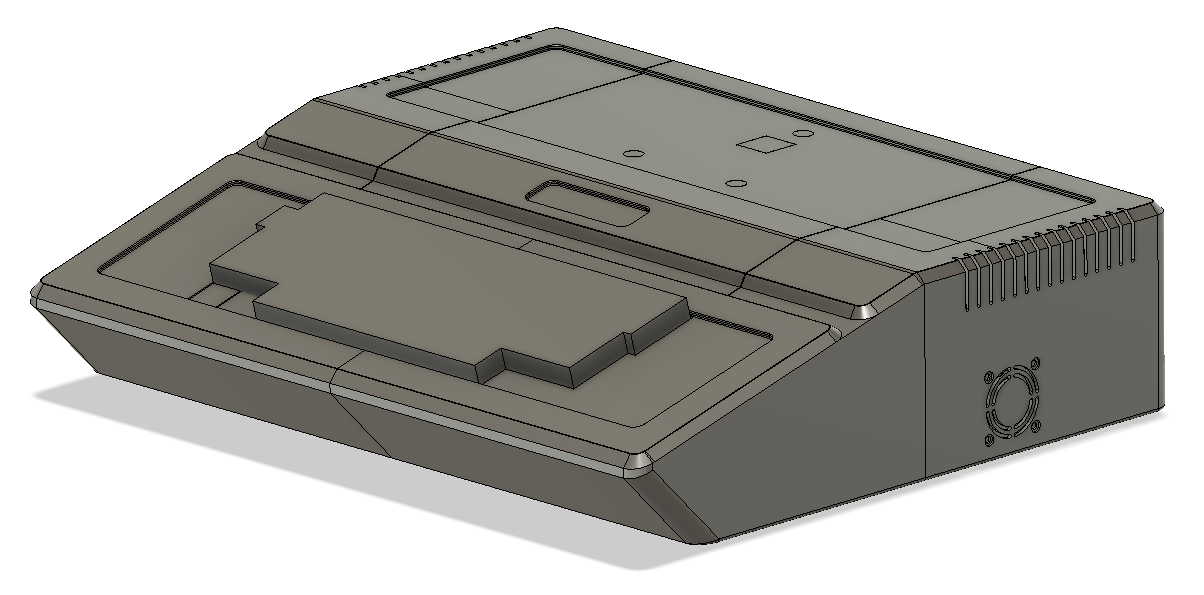
P.S.: Here is the enclosure I am working on (you can see the fan outlet on the side). It is modeled after the Apple II and uses the original Apple II keyboard. Is a bit shorter though.
... of only 80 mA current draw ?
Although I didn't try as I'm not afraid of running the LM323K "hot", you can attach such a feeble load almost anywhere to the +5V / 0V rails in the Apple-1.
It depends on how much uglyness you can endure.
I always cringe when I open up an Apple II and whoever was the previous owner who did the crime, there are ugly loose wires running around, most often for switching the character map. Soldered to some spots on the ICs. Yikes !
Despite it works, it just looks unprofessional and terrible.
So I prefer to connect additional wires where they belong, to connectors. In the Apple-1 you have two options, the J2 video connector, and the edge connector (the one on the PCB itself, not the daughter card slot).
If you use the video connector, you might "see" the current spikes made by the fan in the picture. But this can't be predicted. You must do an experiment to see how bad it gets. If it's too bad, you may try to add a bypass capacitor of 100nF or so at the points where the wires attach to the header that plugs into the J2, and not on the PCB (which would be less effective).
If you use the 44-finger edge connector, there will be no such problem. But you need to buy a header with solder eyelets to make it look neat. These are harder to find than those with pins.
Another option is to solder two wires to the 22uF electrolytic capacitor which is above location D-14 and D-15 in parallel orientation to the big blue 5300uF/15V Sprague capacitor. If you make a neat cable with a connector in it, it will not look too bad. You can make the solder connection on the invisible solder side of the PCB. But be aware that without a strain relief, if that cable is moved too often, it will break loose sooner or later.
If you intend to mount the fan on the motherboard itself you could solder the wires of the fan directly to that 22uF capacitor from above. Note the screw hole near the heat sink, and one of the screws of the LM323K could be extended by use of a standoff, but don't do this on both LM323K screws as the ground connection of the LM323K must be reliable.
So far my 10 cents. Double check that you get the polarity of the fan right. They typically die immediately if reverse polarized.
And thanks for praising my kits ! (Another successful build ! - I now have more Apple-1 clones in the field than Woz himself, but his are the priceless originals, so the comparision is blatant, of course !)
- Uncle Bernie
P.S.: These regulators have thermal protection circuits built in, and so they will turn off if overheated. I never had a case where the LM323K would overheat and turn off, despite I have half height heat sinks on some of my builds, and then run a floppy disk controller card in the daughter card slot AND the 5.25" floppy disk drive off the LM323K. Only the +12V for the floppy disk drive need to be fed from a separate power supply - the Apple-1 runs the 7812 regulator with a far higher input voltage than it needs, so it runs hot and you cannot load the regulated +12V rail any further. This 7812 is the hottest regulator in the Apple-1 (don't touch !), whereas the LM323K is just comfortably warm. It always has been my rule (based on 40 years professional work in the field) that unless an IC is so hot that a spit wetted finger sizzles when it touches the IC briefly, there typically is no need for more cooling. Of course, if you have a well equipped lab, you can use a thermometer in lieu of the spit and the finger. But the finger method is quicker than trying to find the thermometer ! The finger method is adequate for experimental lab and hobby work. Before you finalize a professional product design, you should use a thermal imaging camera to assess the thermal health of the PCB under defined air flow conditions. But hobbyists don't have that type of expensive equipment and some design teams in the industry don't have it neither. The first generation of these cameras needed a sip of liquid nitrogen to work. Which you do have in a well equipped lab, too, but it's tricky to handle, as in case of a spill, you may lose some limbs. Later thermal imagers use Peltier coolers and don't need the nasty liquid nitrogen anymore. Oh, and did you know that some air-to-air missile seekers also needed liquid nitrogen to work ? To be filled up before every flight ? Nice technology, that ! Your taxpayer money at work !
Thank you for your response and all the additional context. I will try using the J2.
GND.jpeg
+5.jpeg
-5.jpeg
+12.jpeg
-12.jpeg
Oh, nice. Thank you! They will come in handy. :-)