
Hi everyone,
I’m currently working on repairing and reverse-engineering an Apple II clock card from the Time ][ / TimeMaster II family, and I’d really appreciate some help from the community.
Initial state
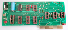
When I bought this card, it was almost completely depopulated:
- most discrete components were missing
- no battery was installed
Rebuild attempt
I repopulated the board using:
- available documentation
- photos of similar boards found online
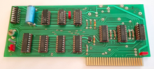
After that, I tried to test it, but:
- the card did not seem to respond
- BASIC test programs from the manual did not work at all
Investigation
After comparing my board with other photos, I noticed several discrepancies:
- diode orientations did not match
- some resistor values were different
Since I couldn’t find any schematic, I decided to reverse engineer the board myself.
During this process, I found that:
- some resistor values made no electrical sense
- diode orientations also seemed incorrect
I’ve included the schematic I reconstructed in this post.

Corrections made
Based on my analysis, I made the following changes:
- R2, R3, R4, R5:
- from 1.8k → 4.7k(pull-ups were too strong compared to M5832 requirements)
- R7:
- from 220Ω → 4.7k
- reversed both diodes
Current status
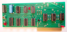
After these corrections:The card is now working correctly !
Remaining questions
I still have two open points where I would appreciate help:
- Battery charging circuit
- What are the correct values for:
- R1
- R6 ?
- I want to make sure the charging current is correct and safe
- What are the correct values for:
- Battery replacement
- What battery should be used today as a replacement?
- Original seems to be a rechargeable NiCd pack
Additional feedback welcome
If you notice anything unusual or incorrect in the schematic I reconstructed, I would be very happy to hear your feedback.
Goal
Once everything is verified, I plan to:
- finalize the schematic
- document the card
- and release everything openly for the community
Thanks a lot for your help!
This seems to be its software: Time_II_Clock_Card.zip
Source: https://mirrors.apple2.org.za/ftp.apple.asimov.net/images/hardware/clock/
There is a Reddit topic, an eBay listing and a second eBay listing with actual photos. I am reposting them here for reference. It doesn't look like your Q1 is facing the right way:
TimeII Reddit.png
TimeII eBay Front.png
TimeII eBay Back.png
In post #1, 'Romain N." asked for comments on component choices and the schematic as such.
I did not inspect the digital logic, as the OP said that the card works, so there can't be a grave fault left there.
But the backup battery and its "charger" circuit leave much to be desired:
D2 is not needed, all it does in the present schematic is to clamp the voltage at R6 to VCC+Vdio, but there is a problem with removing it, see below.
What if D2 was reversed in the original circuit ? If it was, this would power VDD from either +12V or VCC = +5V, which is weird. Why would somebody want that ? I see no reason for that, as in the Apple II, both +12V and +5V both go away when the power supply is switched off. I have no clue what the original designer thought ... why use the +12V supply at all ?
The big lurking problem is that if D2 is reversed from its present state, its clamp action is lost and the +12V will blow up the MSM5832 (VDDabs,max = 7.0) unless the poor NiCd cell volunteers to lose its health trying to limit the VDD voltage. Without the NiCd cell in the circuit, VDD will rise far above the 7.0V limit.
This circuit in its present form can be found in the original MSM5832 datasheet and so the current version of the pdf matches this application circuit of the OKI datasheet. But is is not a good circuit with either polarity of the diode D2.
This whole NiCd charging circuit is terrible and will almost certainly kill the NiCd battery on the long run, by always overcharging it. So your question about the "correct" values for R1 and R6 is moot.
The simplest "safe" charger would use a charge voltage limited to a little bit over the max battery voltage, fed to the battery by a series resistor sized such that when the battery is fully charged, that the current diminishes to just a trickle. Alas, such a circuit won't charge an empty battery quickly. But I think for a computer which is turned on most of the day it still might work OK.
But why would one want to use NiCd batteries anyways, for such a RTC ? I'd ditch it altogether with R1 and R6 and use the two 1N4148 diodes to select either the +5V voltage or the 3.6V from a CR3032 button cell (the MSM5832 will be able to suck it empty until it "sees" only 2.2V left, a which point the button cell will have a voltage just a bit below 3.0V, due to the diode drop, but this is an almost empty cell already, so no waste)
Your choice of R7 is too high to make a good LSTTL 'low' level on LATCH_RST_N. I'd drop Q1 and R7 and wire A2_RES directly to LATCH_RST_N. Not sure why they added that emitter follower, maybe they were afraid of loading A2_RES. But what this emitter follower also does is to decrease the "high" level on its output and if it gets too low, the 74LS174 may always stay in reset. Maybe this was the reason why the card didn't work before you increased R7. But without actual measurements of the levels this is only speculation.
Nice reverse engineering work, though. I wonder if the complexity of this card was ever needed / used - seems it can make interrupts at certain time intervals, selectable by that DIP "mouse piano" switch. A deadly scheme for reliable Apple II operation. Imagine an NMI interrupt while the DISK II is active reading (or, worse, writing) from / to floppy disk (Ouch !).
- Uncle Bernie
I think the general use pattern for retro computers is OFF most of the time, with a few short ON periods in between. This is why if going with the charging option, a modern supercap might be the best approach. Their charging circuits are just as simple and safe.
A 1 farad supercap charged fully to 2.5 V stores the same charge as a 0.7 mAh battery, except that its discharge curve is much steeper and so even less charge is usable to power a memory circuit. Supercaps are usually used to maintain memory over temporary power outages, but the circuits must consume very low currents.
If this type of retention is what the application needs, then it may be practical. If power is lost for more than a day, I don't think it can ride that out very well.
I would not put a single-cell 1F supercap though. I would probably go for a couple of 2-cells-in-series 10F 5.5V supercaps connected in parallel, for a total capacitance of 20F that can be charged to 5V.
Hi everyone,
First of all, thank you very much for your detailed replies and insights, I really appreciate the time you took to analyze my work.
Software test
Yes, I already tested the card with the Time_II_Clock_Card.zip software package.
After the modifications I described earlier, the card is now correctly detected and responds as expected.
About the diode orientation (D1 / D2)
I agree that if D2 had originally been reversed, it could have destroyed the MSM5832 due to the +12V supply.
However, it seems that the person who originally assembled the board actually soldered both D1 and D2 reversed.By chance, this mistake may have protected the MSM5832 from being exposed to +12V.
About the battery charging circuit
I also agree that the charging circuit is not well designed.
My understanding of the use of the +12V rail is the following:
So the idea may have been to ensure a stable supply voltage when the system is powered.
However, as you pointed out, the main issue is that:
Proposed improvement
If I reinstall a battery, I am considering adding a Zener diode in parallel with the battery to clamp the maximum voltage.
What do you think about this approach?
Supercapacitor idea
The idea of using supercapacitors is very interesting.I will definitely study this option in more detail.
About Q1 and R7
Regarding Q1, I must admit that I do not yet have a deep enough understanding of the Apple II bus architecture to fully explain why the original designers added this impedance adaptation stage.
On my board, R7 was originally 220 ohms, which seemed very low to me.
After comparing with photos of similar boards, I more often saw values around 4.7k ohms, which is why I changed it.
However, I am not entirely sure why 4.7k would be considered too high in this context.Could you elaborate on the reasoning behind this?
Thanks again for your feedback, and also for your kind comments about the reverse engineering work.
Any further insights or suggestions are very welcome.
As a follow-up to the battery discussion, I started looking into the supercapacitor option.
According to the MSM5832 datasheet:
If we model the backup supply using a supercapacitor of capacitance C, initially charged to V0 = 5 V, and assume a constant standby current, the discharge can be approximated as:
Valim(t) = V0 - (I/C)t - RI
The RTC remains operational as long as:
Valim(t) >= Vmin
which leads to the general expression for the backup time:
t = C * (V0 - Vmin - R*I) / I
Using:
we get the following approximate backup times:
I find this approach quite interesting, but unfortunately supercapacitors are still relatively expensive for long-term clock backup.
I’d be very interested in feedback from anyone who has already implemented a supercap-based backup on a similar Apple II RTC card.
They are not that much more expensive than the original Varta 3/60DK battery, which has a capacity of only 80 mAh when brand new and would last for about 100 days, if you run the Apple II long enough to fully charge it. For more or less the same price you can get a 450 F Li-ion supercap to operate from 3.8V to 2.2V: https://uk.farnell.com/eaton-electronics/hsh1630-3r8457-r/super-cap-hs-hybrid-450f-3-8v/dp/4574998
Just remove the charging components and replace NiCd with a 3.6V lithium battery. Good to go for 10 years!
In post #7, "Romain N." wrote:
"If I reinstall a battery, I am considering adding a Zener diode in parallel with the battery to clamp the maximum voltage. What do you think about this approach ? "
Uncle Bernie answers:
Could work, but you need to be careful that the Zener diode does not conduct at the highest possible battery voltage, which would drain the battery if power is turned off. The "knee" of the Zener diode may be too soft so it may leak even well below its specified Zener voltage. What Zener diodes guarantee is the specified Zener voltage at or above a specified current (mostly, 1 mA). For operation at lower currents or voltages, all bets are off. Use a curve tracer to characterize your Zener diodes ;-) . . . tedious work with a multimeter can do that, too.
To avoid, you could combine the Zener diode (anode grounded) with a resistor to +5V which would limit the charging and the Zener current and then have a 1N4148 diode (its anode to Zener cathode, its cathode to battery plus) to finish the circuit. This could be dialed in such that it never overcharges the battery but still provides trickle charge. Drawback is that you can't have much current through the Zener, so the max charging or operating current it can provide is limited to 10mA or so (do not overload the Zener, calculate the power it has to turn into heat). If the MSM5832 needs more voltage or current during +5V power on operation of the card than this circuit can provide, then the circuit will be more complicated: you want to give the MSM5832 enough voltage / current while preventing overcharging of the battery and still have trickle charge current left to keep the battery fully charged when the power is on. Throw in the temperature dependency of the relevant characteristics of all the semiconductors and the battery itself, you you have a nice engineering puzzle. This is why there are NiCd battery charger ICs which handle all the issues, including switching a load on/off and telling the load if the battery is close to run empty. Ditching the battery and using a CR3032 (or another Lithium button cell) is definitely easier to do. I'm not sure if your country has banned NiCd cells yet. You might need to use a NiMH battery.
" However, I am not entirely sure why 4.7k would be considered too high in this context. Could you elaborate on the reasoning behind this ?"
TTL/LSTTL input low levels should be below 0.8V, and typical TTL inputs can source up to -1.6mA in that case - LSTTL is less, max. -0.4mA (Iil, "Low-level input current" in the datasheets, the minus sign means the current flows out of the pin). On a 4.7k Ohm resistor this would yield a "low" level of 1.88V volts. High level begins at 2.0V - dangerously close. TTL/LSTTL has a "forbidden" logic level range from 0.8V to 2.0V, and correct function of the gate is not guaranteed in that "forbidden" range. Only Schmitt Trigger inputs can handle the "forbidden" region.
- Uncle Bernie
Great point! There is even enough space on the top right of the card to comfortably fit an AA battery holder.
Please, excuse me for an offtopic deviation but since the conversation turned to draw your battery expertise, I will appreciate some advice on a 1.5V Panasonic MT920 rechargeable battery (it has a different wacth part nunber due to welded custom plate) that I plan to buy for a vintage Seiko watch. I am also wondering whether the original one is a capacitor, or accumulator of some sort, why was it used by Seiko engineers while its life expectancy is about the same as of a cheap watch disposable battery? What I am suspicious about is that being a standard size and voltage I hardly trust that contemporary sources are able to provide replacements that have similar electrical parameters as the original battery:
https://www.watchbattery.co.uk/shop/products/BBCU-302344Z.shtml
https://www.aliexpress.com/item/1005009063336433.html
The first Seiko automatic-quartz design, called the AGS (Automatic Generating System) used an EDLC supercap. Its successor, the Kinetic, used a rechargeable battery cell, but I'm not sure on the chemistry. Lithium-vanadium pentoxide maybe?
Edit: I see it is lithium-manganese-titanium, which is rarely seen.
Either could be called an "accumulator/akku" depending on local language differences.
The idea is interesting, but the rechargeable types don't last much longer than the primary (non-rechargeable) cells used in most quartz watches.
Why would the company use a more expensive and tricky technology when the alternative is just as good and cheaper? Because it was exclusive to them, they controlled it, and it was the basis for the watches' marketing.
With regards to the battery and charging...
I replaced that Varta battery with a coin cell holder for a CR2032.
I've been running it like that for 5 years, no issues and no time loss.
Maybe we're looking into this battery charging circuit a little too hard.
I like Jeff Mazur's solution.
Five years?? How is this possible? A non-rechargeable 3V Lithium battery with a capacity of 210 mAh will only last for about 290 days. Did you put a rechargeable one like this one: https://www.amazon.com/Rechargeable-LIR2032-2032-3-6V-Button/dp/B07JNN842C
Because this machine is on most of the time. The point, though, is that the powered-on state of the card has not damaged the battery. And the battery delivers power when the machine is powered off. I run a BBS (thebrewery.servebeer.com:6400), so the machine is powered on almost all of the time, spending only brief periods turned off for maintenance and backup.
Are you saying you put a non-rechargeable 3V CR2032 battery without disconnecting the charging circuit?
While experience like that is valuable, it may be too hasty to generalize from it to "CR2032 is a safe replacement there". It depends on a lot of things like the effective charge current, and even individual cell variations. Primary cells like "CR"s are not safe to recharge in general, but that is not the same as never being possible to recharge them. Just like non-rechargeable alkaline cells being capable of being recharged in a limited way.
Correct. That's what I'm saying.
It's producing 2V presently. It's probably time to change the button cell.
Here's what it looks like:
Time II.jpg
Incidentally, this card of mine sat in a box for 20+ years because I had no real use for it. The included Time ][ utilities were only useful for DOS 3.3 software. This was really the OG proto-clock for the Apple II.
However, several years back someone from France named Jean-Marc Boutillon created a ProDOS driver for the Time ][, thereby giving it instant utility to me because it could be read as any "ProDOS compatible clock". It now keeps time on my BBS.
I've included the disk image here in case anyone would like to use it. Source code is included, too, which may be useful to you, Romain N.
Perfect - could you measure the voltage across the battery when the machine is on with this battery and also once you replace it with a new one?
Battery ouf of package voltage: 2.31V
Old battery power off: 1.9V
Old battery power on: 5.01V
New battery power on: 2.63V
New battery power off: 2.61V (after being powered on for 5min
Voltage across R1: 1.23V at 220Ω, there is 5.6 mA passing through the resistor so presumably the battery is taking that current. There is some charging occurring, obviously.
I will let it run a few hours and re-test it.
Correction above: Power on 3.63V, power off 3.61V
After several hours running, the voltage drop across R1 is 2.1V, so 9.5 mA
Power off, the cell settles at 3.06V
Yep, that makes a lot more sense.
I manually charge old non-rechargeable 3V Lithium batteries all the time by passing through them around 50 mA, but I would never leave the house and leave them charging unattended. I think it's a little dangerous, even though it’s only 10 mA in your case.
Also old used-up batteries have very small capacity, which is why they go rapidly all the way to 5V when charging and drop to 2V when discharging. Brand new ones however are a different story. They have much larger capacity which is why their voltage is stable near 3V both during charging and discharging. Because of that, they might be more dangerous when overcharging, since you can add a lot more overcharge energy to them, which they might somehow dissipate as heat.
Doesn't seem worth the risk when all you need to do is clip one resistor!
Here is another clock combo card that also uses the M5832 with a 3V Lithium battery. I asked the OP to post the back as well, in case someone wants to compare the schematics: https://www.applefritter.com/content/serial-card-rtc-identification