I got my Apple ii plus up and running and ordered a capacitor replacement kit for the power supply. I was getting ready to start the work and when I opened the power supply, I found it to be prestine. I understand the capacitors can leak and dehydrate over time. But I also am having trouble convining myself to fix something that aint broke and looks perfect.
So before I do anything, I just have to ask: do I really need to do this?
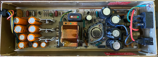
Here's how things look:
Thanks!
Warby
No, you don't need to replace them unless they are faulty. But they may not behave electrically as designed after many decades in storage. Specifically, their electrical leakage may be higher than it should be, because after a long time without power, the aluminum oxide layer that forms the dielectric (microns thick) may have partially dissolved. They may also be physically leaky because the rubber seal has dried or shrunken and electrolyte fluid has seeped down the legs. This is not always obvious because it can be hidden by the shadow of the cap itself. Lastly, they may have partially evaporated the electrolyte, which "drying out" will increase their series resistance and make them heat up more in use. Most often there is no outward sign of any of these, although sometimes leaked electrolyte travels over the board and turns traces from copper to green.
The way restorers deal with the first problem (if the original caps are high-quality, as they are here) is to reform them, a simple process but one that normally requires desoldering the capacitors. A variable voltage power supply, a resistor chosen to pass around 10 mA at the rated voltage (of the capacitor), and the cap to be reformed are connected in series. Then the supply is turned on, and the voltage drop across the resistor is monitored. The voltage across the resistor is proportional to the current in the circuit (the capacitor's leakage). If after several hours the leakage falls to around 10 µA, it has been successfully reformed.
The other problems (leaky rubber seal and high ESR) aren't fixable and they should be replaced.
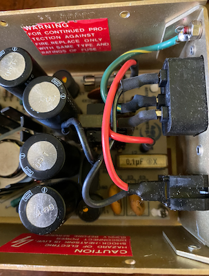
The big boxy yellow colored on marked 0.1pf X should at least be replaced because if those fail they are very smelly and gross to clean up.
The electrolytics look fine, but if you decide not to re-cap right away I'd check again after some usage and see if any signs of bulging or leaking develop.
If a picofarad capacitor blows up or goes bad, it must mean it is the end of the world.
Treat yourself with an ESR meter and measure the values of the capacitors. You will not regret owning such a tool.
Replace the film capacitors regardless as they will most likely fail if they haven't already.
Take a close look at the yellow RIFA capacitor.
If the plastic casing has small cracks you should replace it immediately.
If it's an old one it will have cracks and it will blow up sooner rather than later.
A good one has no cracks in the plastic casing.
Example of cracks (just a random cap, probably not the same as in your psu):
rifa-cap-with-cracks.jpg
Thanks everyone for the feedback. I did replace the 0.1 µf (micro farad) RIFA capacitor and will purchase an in circuit capacitor tester before I mess with the others.
Here's the original cap:
Screen Shot 2022-01-14 at 3.47.08 PM.png
Here's the cap removed (super nice there was pre-drilled holes for the narrow spacing of the new cap):
Screen Shot 2022-01-14 at 3.47.17 PM.png
Screen Shot 2022-01-14 at 3.47.23 PM.png
And a view of the new capacitor:
Screen Shot 2022-01-14 at 3.47.33 PM.png
I did a load test with about 0.5 amps of load and the +12 volt supply did dip from about 12.9v no load to 11.4v with load. Any reason to be concerned with that drop? (the 5v supply stayed >5v with a load.)Also, anyone recommend a good make/model of in circuit capacitor tester?
Thanks!
wabry
IMO, if you're going to spend the time trying to test the caps, you might as well replace them. Also, you'll be amazed at how much smaller the new ones are. Not to mention, the originals were all 85c. Replacing with 105c caps should last even longer than the originals.
Ancidotaly, I just recapped a IIe supply that based on the sticker was from late '84. I scoped the rails (unloaded) before and after the recap. I did see a slight decrease in noise on the positive rails (which weren't that bad to begin with). But I also saw a slight increase on the negative rails. I don't really understand why the negative rails would get slightly worse. Unloaded voltages also increased just slightly. But remained about the same before and after when hooked up to the motherboard idling.
Personally, anything older than 30 years old I like to recap as preventative maintenance. Coupled with the fact my eyesight and motor skills are still good now. 10 years from now, who knows what they will be like. But at this point at least I can comfortably say capacitor issues will be the next guys problem, not mine.
But ask 10 people on how they handle this situation, you'll get 10 different answers
I have used the EDS 88A CapAnalyzer II with success. Note that it comes with instructions that must be kept in mind because it is not a "point and shoot" instrument. A somewhat lower-cost alternative is the Anatek Blue ESR meter, but it also requires careful technique to use. Another choice would be the Midwest Devices Capacitor Wizard, a slightly larger device. Also note that some common "LCR meters" like the DE-5000 and the U1733 can't be used in-circuit.
Many multi-rail power supplies do not regulate each output voltage separately, but only regulate the "main" voltage, and derive the others from it. So if you only put a load on one of the other voltage rails, it will sag from a lack of load regulation.
Thank you for this suggestion, and this thread. I've undertaken a project to resurrect my old Apple ][+ from high school, and it's proving difficult. Every time I boot (no floppy drives) I get green squares on the screen. This was both before and after I replace the 0.1 uF RIFA cap because it literrally went up in smoke. I helpful person on Twitter thinks I might still have a problem with PSU, so I think I'll just replace all the caps. (I bought the whole packet.) If anyone's seen these green squares before, and might have an idea what it could be, I'd love to hear it.
FICTiXCUYAAwHoC.jpg
My first thought is faulty ram.
Run a diagnostic program to test the ram.
Also try to reseat the ram ICs if you haven't already done that.
What voltages does your power supply meter out at?
Thanks! That was my first thought, too. However, given how it seems to 'pop back' upon "reset," I'm thinking the issue might be the PSU. There's a decent chance it's both. After replacing the caps (probably not a terrible idea regardless) I'll reseat the RAM ICs. Can you recommend a diag to test the RAM? For that, however, I imagine I'll need to get the floppy drive to work. That's going to be another problem.
Thank you for the question. For this I'm guessing I need a multimeter, correct? I was going to look try to pick up +5V and ground off the motherboard to check that out. Please let me know if I haven't got that correct.
Yes, you need a multimeter. That's not as expensive as you might think, and you really need one for this kind of work. They are not a Fluke 77... but the under $20 ones that Harbor Freight sells work and are adequate for this purpose. There are other sellers, and you should be able to find something under $50 even if you don't have a HF near you.
If you can get to a monitor prompt, you can type in this memory test code (found in another thread on Apple Fritter):
C050 C053 C054 C057 N 265:FF N 266<265.BFFEM 266<265.BFFEV 265:0 N 266<265.BFFEM 266<265.BFFEV 34:14 (Return)
There's a space before you hit return as I recall. I also wrote a dumb basic program that does peeks and pokes and plots the results. But it's slow and assumes you have the boot ROM and can get a BASIC prompt. Let me know if you might like that one.
HTH,
Warby
Normally there is no need to replace any capacitors in an Apple Astec power supply. Even though they are old they are of sufficiently high quality and are specified well within their operating parameters for voltage and temperature.
I always say that "recapping" for the sake of doing it has an equal chance that you will either make the device better or make the device worse.
This is because you don't normally have the luxury of culling out parts that are of marginal spec, the parts you select may not have been as good as the parts you replace, or you simply cock the job up with poor workmanship.
What happened in this case is unknown. But you made your power supply better AND worse at the same time.
Incidentally, there is one capacitor (apart from the "RIFA" noise reducing capacitor on the mains-in) that fails with regularity, and that is the 220 uF 10V cap, often referred to as C7. It sits beside a power resistor (and is marginally specced at 85°C and 10V) so it gets hot and sometimes fails. It should be replaced with a 105°C, 16V version.
Thank you, baldrick. It difficult to know what to do. I've seen others say that those cap dry out of decades and that it's probably a good idea to just replace them all. I purchased https://console5.com/store/apple-2-power-supply-cap-kit-p-n-605-5703-astec-aa11040b-aa11040-b.html, so I have all the caps and am reasonably confident in the quality. As for the workmanship, that's a bit of a concern, but I've got a friend helping me and we've got the right tools. I'll just need to make sure that I don't plug anything in backwards. Perhaps I'll just do the C7, but once we get in there we'll probably do all of them.
It's not 100% clear that I have a PSU problem. https://twitter.com/bzotto/status/1483333663135715332?s=20 was what got me going down the path to just replace all the caps. I'll see if I can run that mem test.
Thank you, Warby. I saw that too. First, I had to power on/off several times before I got a prompt that would work. (After it does work, however, further on/offs seem to continue to work, which makes me think the machine needs to 'warm up', which make me think there's a PSU issue.) Anyway, I typed in the code, very carefully, and my screen went like the image below. The speaker was beeping like crazy, so after about 10 seconds I turned it off.
I also thought of putting together a little BASIC program to scan the RAM with peeks and pokes. It would take me a long time to figure that out, so should I ever get the floppy drive working, I'd love to take you up on your offer. Thank you.
PXL_20220121_043306599.jpg
I mean, I'm talking like a +/- 5, maybe 10mv change on each rail. And these rails are already low noise. Like maybe 40mv? So it's not like it drastically made things better or worse. And that is based of what my Rigol is calculating. I'm sure there is a bit of margin of error there. I don't look at scope traces enough to visually tell what is better or worse, especially in a small change like this.
These psu caps are pushing 35-40+ years. And to your point, are all 85c and stuffed in a metal can that traps heat. Even if they are good Nichicon or Rubycon caps, eventually they will fail. Best case they just fail open or values drift and nothing gets damaged. Worst case they short and cause other components to get damaged or they leak all over the PCB and eat traces or other components that will need to be bodged/replaced. At what point would you consider preventative maintenance of replacement capacitors to be acceptable to avoid issues?
I'm curious about C7. You said it's marginal at 10v. What does it run at? I opened my PSU to measure across C7, but didn't feel like trying to wrestle the PCB out again. Looking at the schematic, I should be able to measure the voltage across that cap by measuring the cathode of D1, and one end of R6 (which end is not clear from the top of the PCB). I measured both ends of R6 to D1 and my DMM only registered something in the millivolt range on either end of R6. This was unloaded, so either it ramps up when under load, or it doesn't seem to be running even close to 10v. Of course my method of trying to figure this out is not perfect either. So it could be an issue in my methodology.
I don't consider it. It popular dogma that capacitors "eventually fail", but I have equipment with capacitors that are older than me (and I'm in my 50s) that work perfectly and the electrolytic capacitors are still in spec. I've found that capacitors that sit idle for very long periods of time don't last as long as capacitors that are in-circuit, in-operation and are operated within their design critera.
Exceptions are, of course, modern cheap components of questionable provenance, factory rejects sold on secondary markets as good parts, and most "off-brand" chinese stuff.
I will be first in line to say that a Mac SE/30 or Mac IIFX "needs recapping" immediately, but a quality part like the Astec Power Supply? Less so.
With regards to C7, it appears to be needed to set a reference the oscillator at power-up. Without it, the power supply does not function at all.
Someone will come forth and correct this statement, I'm certain...
Electrolytics can fail with age but that does not mean all old electrolytics are on their death beds and should be replaced. If there is no physical sign of leakage or deformation, and the electronic equipment still works perfectly well, if it ain't broken don't fix it, unless you just like "make work".
I have audio equipment from the early 70's and Apple IIs from the late 70's and early 80's that still have their original e-caps and work perfectly well. The best thing you can do for an electrolytic is to use it, exercise it (charge/discharge), e.g. turn the equipment on, let it run for several hours, turn it off, repeat for several days. Do that every few years or at least keep 'em in climate controlled environments when not in use.
When you get an old Apple and you do not know what kind of life it had, but it looks clean and runs well, that might be a different story as to what makes the most sense to ensure it keeps running well, but I've replaced bad electrolytic caps with new/old stock caps that are 60 years old and they work fine.
Like someone stated earlier, when it comes to caps, and ESR meter is the best friend you can have, or a multi-amp, current limiting, variable DC power supply, some resitors, a multi-meter and a watch with a second hand on it will suffice as well.
I agree with, "If it ain't broke..." Common sense. But what if it is broke?
Prior to a couple weeks ago, my Apple ][+ hadn't been powered up since the 80s. It's been stored in a non-climate-controlled garage for a decade. I've pulled out all the cards and it's still not operating correctly. When I first turn it on I get random green squares on the monitor and nothing works. If I press 'reset' a few times, and power it on/off a few times, I can get it to a state where it looks mostly right and can run BASIC commands. This makes me think it needs to 'warm up', which is apparently a charitaristic of worn out caps.
I really don't want to perform hear surgery on the PSU, and now I'm nervous that my 'moden' replacement caps are of "questionable provenance and quality," but from my naive perspective this is feeling like a PSU issue.
I could test the old caps, but I'm actually not sure how to do that. My guess is that they would need to be removed from the PCB and isolated in order to check their properties. At that point, might as well just replace them. My PSU is schedule to go under the knife in 1 hour, so for the moments that's the plan. I'll label and save all the old parts. This is going to be an adventure. In case anyone is curious, I'll report back here. Wish me luck.
Have you metered the power supply? I wouldn't assume it is the problem unless you are seeing incorrect voltages. I would definitely replace the RIFA caps, but unless the electrolytics show signs of bulging or leaking I'm not sure I'd mess with them.
I assume you have re-seated all the chips? Checked for any that might be getting hot? Showing green bars or blocks is often a sign of a bad RAM chip, especially in the lowest 16k bank. It can also be one of the logic chips that does RAM address decode, etc., or something entirely else though.
This book PDF might be helpful to you:
https://commodore.bombjack.org/books/apple/Apple_II_Plus_IIe_Troubleshooting_&_Repair_Guide.zip
Thank you! That PDF is amazing. I will have to sit down and spend some time going through it page by page.
In the meantime, the PSU cap operation was a success (https://twitter.com/markdcramer/status/1485306935968600064?s=20) but the patient is still sick.
I'm not sure what "metering the power supply" means, but I checked voltage across a random chip (upper-right to lower-left pins) and got +4.8V. That seems good. I did the same across a RAM chip and got -11.5V. Not sure why it was negative. Anyway, I should look into that more closely, but the machine turns on and runs, so I'm thinking it's good.
I have not re-seated (I assume that means you pull it out, clean it and plug it back in) any of the chips. Perhaps that would be next. I'll go through them one by one and take a very close look. I'm thinking I should get a tool for that.
I appreciate all the help I'm getting on this board. Thanks!
FJzdbHwVQAAPmP3.jpg
The Troubleshooting and Repair Guide is a great road map! The green squares or other random chacacters on the screen is ofen a bad RAM chip or perhaps (less likely) a failed 74LSxxx chip. Fortunately, most replacement chips are cheap and easy to get. I suggest the following approach. Unfortunately, there is not built in test for RAM on the Apple ][ Plus like there is on the //e.
1) Hot chips = failed chips. Turn it on for 20 minutes and then check the temperature of each chip using your finger. Bad chips are often noticably hotter than working chips. While not definitive, this at least narrows things down quite a bit. Fancy chip tester are nice, and I have one, but often not needed.
2) Turn the computer off. Remove, clean and reinstall any hot chips as detailed below. Many times this fixes things. Otherwise plan to replace hot chips.
3 )With power off, remove all RAM chips, laying them out so you can put them back where they came from. Note the orientation of the notch on the top of the RAM chip. If you have a 16K memory/language card, disconnect the ribbon cable from the motherboard also. Look for black or other corrosion on the chip legs and sockets. Corroded sockets can be cleaned with contact cleaner (I prefer Deoxit) or replace by desoldering the old one and replacing it. Cleaning is a lot easier than soldering and it often works. I clean the chip legs with contact cleaner & Q Tip, and by scuffing them lightly with a fine emory board.
4) Begin reinstalling RAM one row at a time beginning with the row nearest the keyboard. Only the first row is critical to boot. If it fails to boot, try replacing with a different row of RAM. The RAM chips are interchangable. There is a very good chance your problem is in the first row of RAM now. While it is possible you have at least one bad RAM in each row, it is unlikely and one of the rows is probably good.
5) Now RAM test software can be used or you can proceed to reinstall each row and check function one row at a time. Replace individual suspect RAM chips with trusted ones. All chips in the row need to work.
I won't be able to get to this till next week (job and stuff), but wanted to give a quick thank you for this great advice. I'll get myself some Deoxit and a tool to remove the chips and then report back. Since this is no longer PSU capacitors, I'll create a new thread.
Keep in mind that you can't just randomly measure pins on each chip and assume they are the same as the last chip you checked if they are not the same part number. If you look at the schematic or datasheet, you'll have a better understanding of what you are measuring. Looking at a 4116 RAM chip datasheet, "upper right" would be pin 16, VSS/ground. "lower left" would be pin 8, VDD/+12v. If you had the positive lead on the upper right/ground and negative on the lower left, then your meter would see it as -12v. Which lines up with what you are saying you saw.
4116.png
Thank you, Nick! Yes, you are absolutely correct. During my EE days I recall ground always being the lower left and Vcc always being the upper right, but this one is obviously different. Thank you for pointing that out. The good news, however, is that the -11.5V reading seems to be relatively correct. I must have another problem elsewhere, so this weekend I'll try to follow the advice above and go through the RAM chips.
Hello Warby - Thank you for this offer! I've started another tread about my RAM issues, but I'd love to try out your BASIC diagnostic program. Please let me know what I need to do. Thanks!