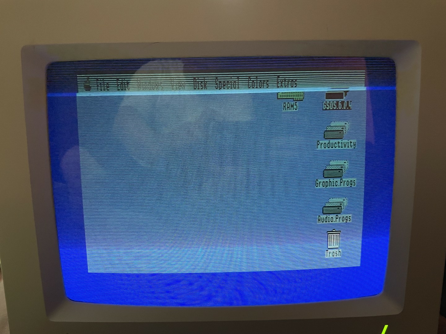
Yesterday I was using my IIgs and around the time of a reboot, I noticed horizontal lines looking like a comb at the top of my screen (I later found out this is called "folding over" in CRT terms. i used the vertical size adjustment on the monitor to get rid of them, but then noticed I was left with an image where things looked squished vertically, and the image seemed to be off center. There was a larger blue border at the bottom than top.
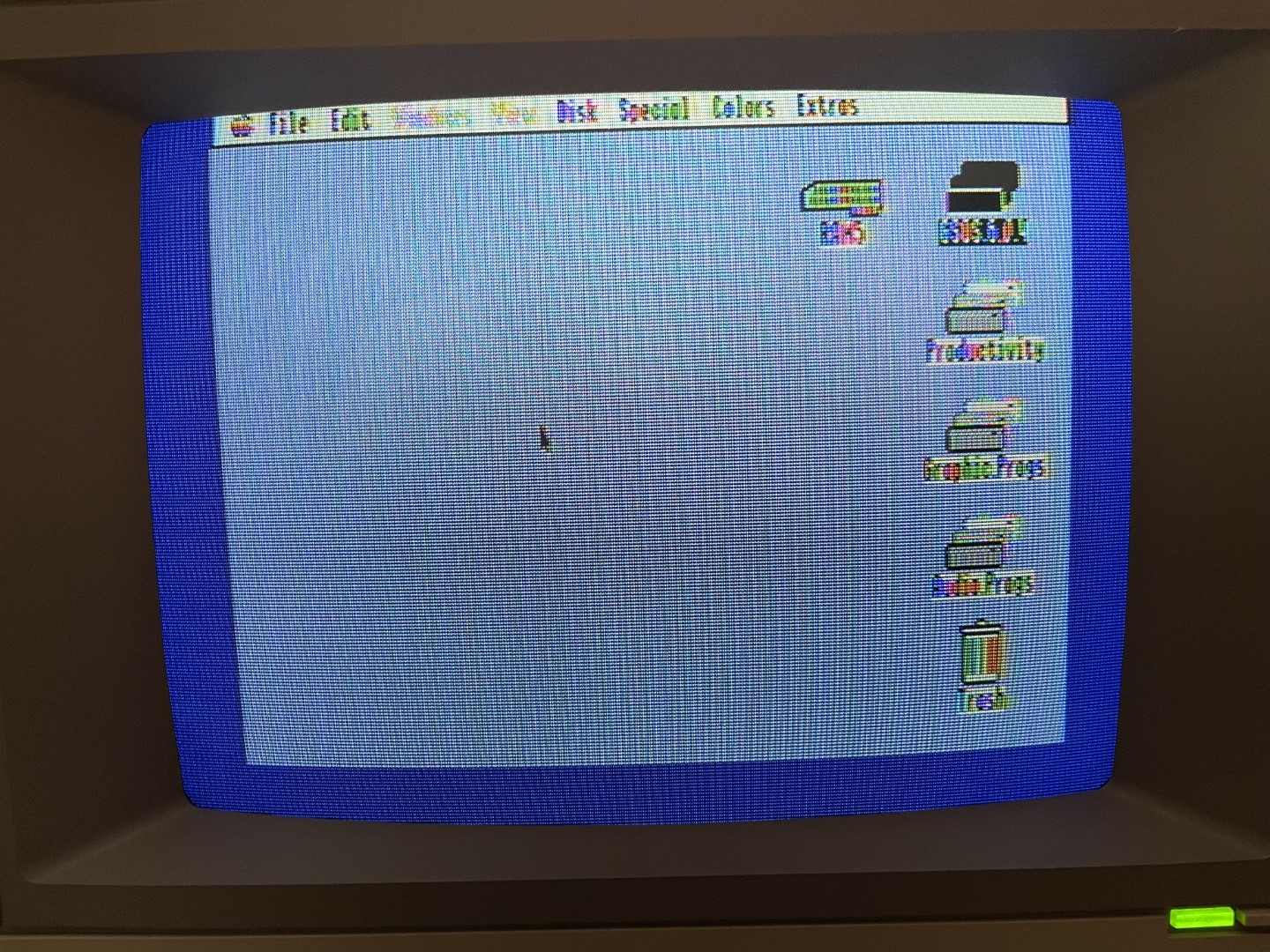
Thinking something in the vertical deflection failed in the monitor, i grabbed a spare monitor (that was previously adjusted for this IIgs) and hooked it up. I had the same folding over issue. I tried a different, thicker monitor cable, no change. I then hooked up my color IIe monitor to the composite jack. While this monitor did not show any fold over symptoms, it was clear the top part of the screen was getting clipped off and not centered properly (I never really used composite on the IIgs before, so I'm not 100% sure exactly how the image should "fit" on the screen compared to the RGB - but this doesn't seem right).
Given that multiple RGB monitors, cables, and composite seem to be exhibiting the issue, I can only assume something went wrong in the IIgs video path. I'm really hoping maybe some passive part went bad/out of spec some how. But I really don't know video circuits, so I'm hoping someone here might be able to help. Both the IIgs PSU and mainboard were recapped about 3 years ago. All the monitors used in testing had also been recapped at some point in the last 3 years as well. It is a ROM3 (if it matters) and a schematic of the ROM3 is available over at Reactive Micro.
Luckily the ROM3 has many test points around the video output circuit that can be probed to check its operation.
I can't see any distortion in the pictures after the first. Could you describe the problem in a little more detail?
If the RGB monitor is folding over, there may be a problem with the timing or voltage of the vertical blank period. I guess that points the MC1377 or its surrounding passive components.
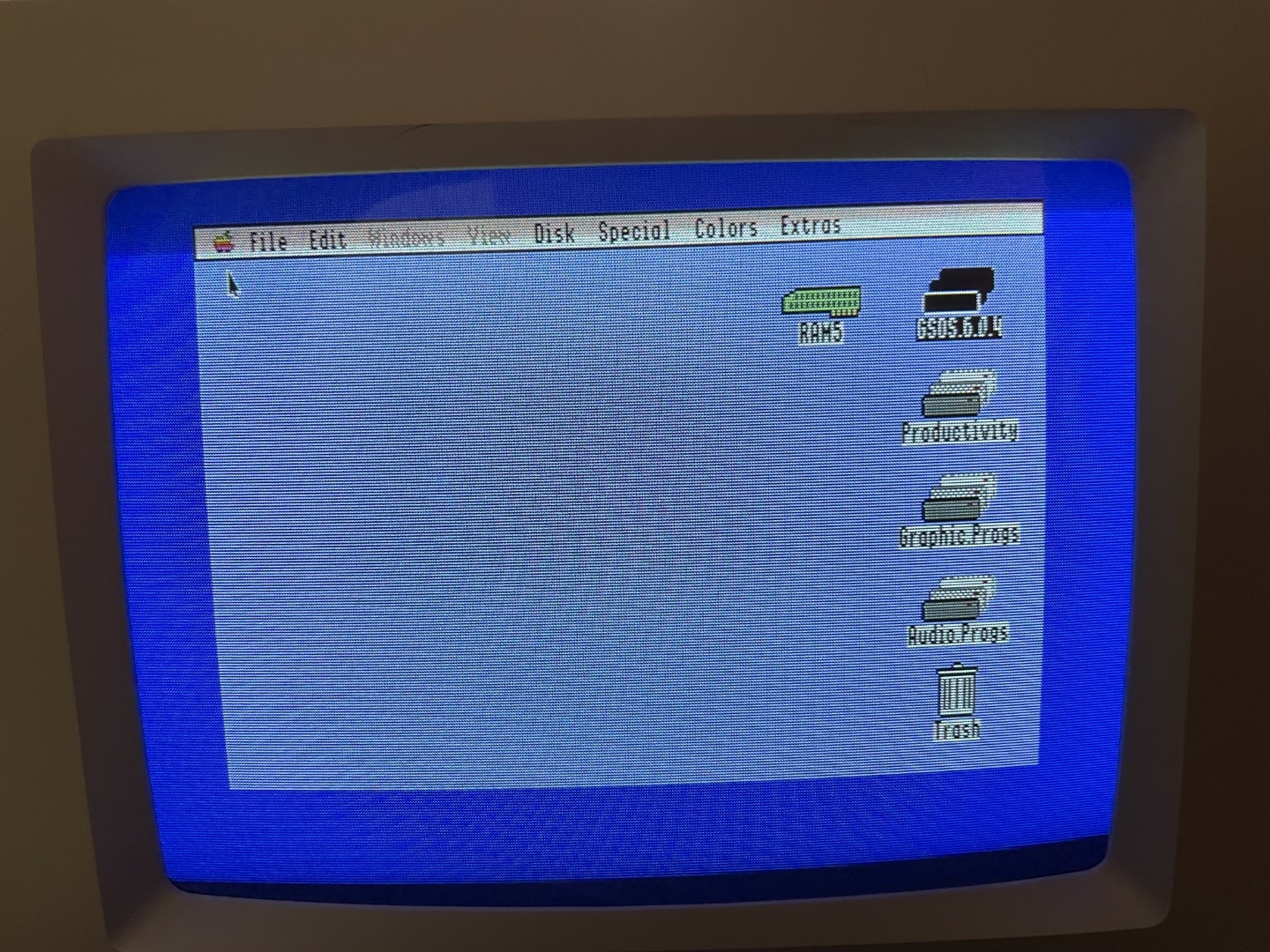
The main issue is that out of no where, the RGB monitor began folding over. As did a second monitor that had previously been adjusted to look perfect in this same IIgs. In order to get it to stop, I had to cut down the vertical size. Which left me with a slightly vertically compressed image. I know it's kind of hard to see in the picture. But it definitely looks not right in person. Text clearly looks shorter that it should be after adjusting the vertical size.
Additionally, the border at the top is much thinner now than the border at the bottom. Making it seem like the IIgs shifted the entire image up. Which I think caused the fold over. The composite monitor also seems to have the image shifted up vertically as well, it just cuts off instead of folding over.
Does your IIgs have a battery? The MC1377 is near the battery and could be damaged by battery leakage.
Isn't the video timing being controlled directly by the Mega II? It could also be a bad VGC. Looking as the schematics, I can tell you that you will definitely need an oscilloscope in order to diagnose this.
The battery never leaked in this IIgs before I owned it (at least from what I could see), and I remote mounted it shortly after I acquired it. I did see it looked like the Mega was the ultimate source of the sync signal. I'm still hoping it's maybe something passive and easy to replace, but my luck doesn't usually run that way.
I have a Rigol 1054z scope. I'm just not very good at using it. I mostly just connect it up and hit the auto button and hope I get something useful. I can grab some screenshots off it for any points of interest if someone can tell me where to look, and if I should have anything specific on the screen at the time.
At the risk of showing my ignorance of video signals and scope usage, I went ahead and took a couple snapshots of anything labeled sync on the Mega II (pin 50) and VGC (pin 6). Not sure if these show anything useful or not. The GS was just sitting at the check device screen with the apple going back and forth.
Mega II pin 50 Sync Scope.png
VGC Pin 6 Sync Scope.png
Ok, this is good, but we need to go back a little and establish a reference, which in my opinion should be the output composite signal itself.
I have written this little program in BASIC precisely for fixing issues with composite video. You should be able to run it in you Apple IIgs:
5 GR : POKE 49234,0
10 COLOR= 15: GOSUB 100
20 COLOR= 13: GOSUB 100
30 COLOR= 7: GOSUB 100
40 COLOR= 12: GOSUB 100
50 COLOR= 11: GOSUB 100
60 COLOR= 9: GOSUB 100
70 COLOR= 2: GOSUB 100
80 COLOR= 0: GOSUB 100
90 IF PEEK (49152) > 127 THEN GR : HOME : END
95 GOTO 90
100 FOR X = OFFSET TO OFFSET + 4
110 VLIN 0,47 AT X
120 NEXT X
130 OFFSET = OFFSET + 5
140 RETURN
It will generate the standard 8-color pattern (or as close to it as an Apple II can do):
Pattern.png
If you hook up channel 1 of your oscilloscope to the output (with the monitor also plugged in) and setting the trigger right below 0V you should be able to see this:
Composite.png
And when you zoom in a bit:
CompositeZoom.png
The dip that you see more or less in the center which the trigger detects is the vertical sync signal and the tall chunky rectangles are the individual frames. I expect this dip in your case not to be in the center, but all the way to the right or missing.
Once you have this, you can use channel 2 to look at other signals relative to this one.
Thanks for the info. I attempted to capture similar traces, but mine look a bit off. I disconnected the RGB monitor, plugged in a composite monitor, ran your program, grounded the probe to the metal fingers that usually contact the PSU (I confirmed they have continuity to the outer composite jack ground), probed the back of the jack on the center, hit auto, set my scope up similar to yours, then hit single to capture a single frame. Do these make sense?
IIgs Composite 1 5-25-23.png
IIgs Composite 2 5-25-23.png
Yep, this is precisely the oscillogram I wanted to see.
That slow rise right after the vertical sync is definitely causing the problem. At this time scale the rise should be instant and your last oscillogram should look like this:
Newfile8.png
I have to take a look at the schematics. I am suspecting an electrolytic capacitor has gone leaky and is resisting being charged, but I am not really sure at this point.
Btw, make sure channel 1 is set to DC, not AC. Don't use Auto. I think Auto might be setting it to AC.
With channel 1 connected to the composite output and displaying the oscillogram above, can you connect channel 2 to pin 2 on the MC1377 chip to see how they look together? Make sure channel 2 is set to DC as well.
The idea is to find a slow rising impulse that matches the rising rate of what we are seeing on channel 1.
The channel was set to DC, it shows either a DC icon or sine wave icon next to the channel numer at the bottom of the screen print. And in the upper right of it, I had the trigger set to -48mV like in your snapshots. I think that was all good. Like I said, I'm not very good with scopes.
Anyway, I grabbed a snapshot of pin 2 and composite at the same time. Based on what you are saying, I believe the signal is normal at MC1377, as there only seems to be a signal during the point where channel 1 drops down. It's not showing anything during the slow rise, correct?
IIgs Composite and MC1377 pin 2.png
Can you also check pin 9 of the MC1377? I am starting to suspect C6:
C6.png
I'm assuming the video out is probably the same on ROM0/1 and 3, but this schematic looks dawn differently than the link I pasted in my first post which has a 3 schematic. I'm guessing this is a 0/1 schematic, but a quick glance does make them look the same though in this part of the circuit. Just mentioning it incase they did tweak anything (extremly unlikely).
The slope is present at pin 9. I did have to increase the vertical on channel 2 to 2V to be able to see a wave form. I had recapped this entire IIgs about 3 years ago, using high quality caps. Not to say C6 couldn't have been a bad cap despite it being new 3 years ago. Every manufacturer has a certain failure rate. Would this cap also affect the RGB output? I do see from C6 it does go to RGB pin 12, which seems to be labeled "monochrome video out" on the pinout I found. But I also see RGB has it's own composite sync on pin 3. So if there is an issue with C6, how could it affect the sync on RGB? Or is pin 12 still used somehow by the RGB monitor? Not questioning your diagnosis. I'm just trying to wrap my head around this.
IIgs Composite and MC1377 pin 9.png
I am not sure where is the VSYNC on the RGB and I don't have an Apple IIgs to see what kind of signals it produces. Perhaps you can check. Try to find this slow rising situation on the RGB pins.
I was looking at the schematics from here, which is what Google gave me:
http://cini.classiccmp.org/pdf/Apple/Apple%20IIgs%20schematic.pdf
Looking at the RGB cable I have, pin 12 isn't even populated. So the shifting on RGB seems to be coming from somewhere else. Looking at the schematic, it looks like Sync to RGB comes out on pin 3. I could clip on to a leg of L12 (which conencts to pin 3) and take a snapshot there. I had both monitors connected and on, if it matters.
Unless I don't have something set right, this symc looks different than what we were seeing when looking at the composite signal. I don't see any slopes, unless I have the horizontal time set incorrectly.
IIgs L12 RGB sync.png
This looks like the HSYNC, not the VSYNC. Always keep channel 1 either on the composite output or on pin 9 of MC1377 for reference and use channel 2 to explore different signals.
Hmm, I'm not really sure where to look. Any suggestions based on the schematic? The RGB cable I have only has the following pins populated, along with these descriptions of the pins from what appears to be an Apple manual:
1 - Signal Ground (R)
2 - Analog (R)
3 - Composite sync (schematic lables this COMSYNC)
5 - Analog (G)
6 - Signal Ground (G)
9 - Analog (B)
10 - (odd the cable is populated)
13 - Signal Ground (B)
Excuse my video signal ignorance yet again. Pin 3 should have the combined V/H sync, correct? None of the other pins are labeled sync, let alone vertical or horizontal. I always thought analog RGB used a combined sync, where as digital RGB used separate V and H sync. or is the vertical sync some how combined into the RGB signals?
I see the sync coming in on pin 2 of MC1377 also goes to pin 3 on H1 (the proper term escapes me right now, but it's one of those in-line components where you can see little rectangles poking out - like integrated resistor and capacitors), which seems to generate the RGB signals. The same sync line running to MC1377 pin 2 also splits off to a 2N3904 transistor (Q3, which is unfortunately on the bottom of the board and I can't easily scope) where the emitter then feeds pin 3 on the RGB (after passing through a few more passives, including L12 where I took the last snapshot).
I am not sure, maybe the VSYNC is contained within each R, G and B, or maybe pin 2 contains both the HSYNC and VSYNC. I couldn't tell from the oscillogram in post #12, you really need to zoom in on this part:
IIgs Composite and MC1377 pin 2.png
Also what do the oscillograms of R, G and B look like?
The print with only channel 1 is a zoomed in shot of just pin 2 on MC1377. Based on what you said, this appears to be only horizontal?
The print with both is composite on channel 1/yellow, and green is on channel 2/blue. It looks like maybe the vertical sync is in with the RGB signals then?
IIgs MC1377 Pin 2 Only.png
IIgs Composite and Green.png
It has nothing to do with digital or analog and everything to do with where the sync separator is designed in the monitor. The Apple IIgs RGB Monitor uses composite sync. "Composite" means "made up of various parts or elements": in the context of sync signals, the elements are horizonal and vertical sync carried on the same wire.
It is possible to dispense with the wire for composite sync altogether and use one of the color channels to carry sync signals, which is most often known as Sync-On-Green because these schemes almost always use the green channel.
Those H components are Hybrid ceramic circuits. I think they are just video amplifiers and the H1 may also be adding sync to the green signal.
Looking at pin 2 only on one channel is not very useful, since without a reference there is no way to know exactly where we are in the very complex composite signal that makes up the picture.
The second oscillogram is very useful though. Channel 2 seems to have everything a monochrome composite signal needs. This means you can connect just the Green from RBG (plus the ground of course) to your composite monitor and see if the picture is good or shifted up. From what I can see in the second oscillogram it should appear correctly.
Feeding the green signal into the composite monitor just gives me a black and white pattern of the color bars. It's still shifted up as far as I can tell. I just measured, and in both cases the bars started an inch off the bottoms bezel. So there was no change in vertical position between full composite, and feeding green into the composite monitor.
That makes no sense though. The top margin is determined by the distance indicated by the two red arrows bellow and my oscillogram from my Apple IIe aligns perfectly to yours:
Allign.png
Maybe it has something to do with the VBL: http://www.1000bit.it/support/manuali/apple/technotes/iigs/tn.iigs.040.html
It looks like CVT has the background set to black while Nick's is still the default blue. I know this isn't the issue, but it might be interesting to see if there is any change if Nick changes the background color in the control panel. Or for that matter, changes the control panel to a monochrome display.
i think Jeff is right. I didn't even consider the whole IIgs background and border colors. I now set them both to black, and here is a snapshot of composite in yellow, and the Green signal in light blue on the scope.
IIgs Composite Green Black Background.png
And how does the centering look on the monitor?
IMG_3379.jpeg
Ok, so assuming that the problem is not caused by the slow rising signal (which I no longer think it is), it must be caused by a delayed VSYNC, which is contained together with the HSYNC and is coming out of pin 6 of the VGC. It is then used both for the composite and the individual RGB signals:
Sync.png
So, the cause must be the VGC itself or something before it.
Is the vertical position of all your monitors at maximum?
The monitors don't have a vertical position adjustment. On the back there are only 3 adjustments. Vertical hold, vertical size, and horizontal hold. V hold doesn't move the picture at all. It just goes from stable to rolling at some point. V size gives the illusion that the picture is moving vertically, but when adjusted for a normal text height, I get fold over at the top.
Looking at the schematics, there seems to be something inside the monitor labeled V-POSITION:
https://www.applefritter.com/files/2022/07/21/%5BApple%5D%20IIgs%20RGB%20monitor%20-%20Schematic%20diagram.pdf
Something.png
I guess if there is no easy fix on the IIgs itself, I guess tweaking that adjustment in the monitor may be my only option. I was hoping to avoid that, since the issue is clearly with the IIgs. But if the VGC is at fault, then there is no easy fix.
If you are lucky and find a pot inside for the vertical position, it will be the easiest fix of all possible easy fixes!
They do have a pot for the horizontal position and even one for the vertical linearity. It would be really strange not to have something for the vertical position.
Yeah. Adjusting the pot in the monitor is easy. It's just more treating the symptom than curing the cause. Because any monitor that now gets connected to this IIgs would need the same adjustment.