| Attachment | Size |
|---|---|
| 1.08 MB |
Having received replacements 2504v ICs and 7400s, I got the video section apparently working as per the bring up guide. I then completed the computer section.
On powering up, everything seemed OK. I got the usual flashing @'s and the CLR function (pin 12 to pin 16 on the KBD connector) cleared the screen as expected. Also the RST function (pin 1 to pin 9) worked as described.
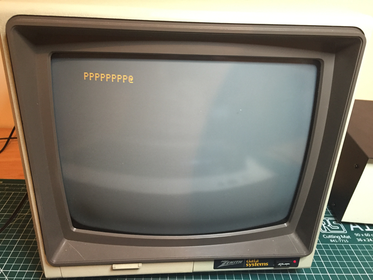
I then decided to build the PS/2 keyboard adaptor. With this connected, entering CTRL-C-L-R cleared the screen. However, using CTRL-R-S-T just produced extra P's on the screen (see picture)

I then disconnected the keyboard adaptor and restarted. This time shoring pin 1 to pin 9 just produced P's again. I then had another go with the keyboard adaptor. Now, the keyboard was completely dead and the microcontroller was scalding hot. I have now disconnected and abandoned that.
Working without a keyboard, RST still produces P's. I have swapped the 6502 and 6821 chips (for known working chips) as obvious culprits for a failed RST function but the result remains the same.
For what it is worth, I have meticulously checked the wiring patches on the keyboard adaptor and they are all correct with no shorts.
I would welcome advice. I fear somewhere along the line I have damaged some previously working components.
Had a closer look at the PS/2 keyboard adapter. I hooked it up to my variable PSU (set at 5v of course) with no keyboard and no Mimeo-1. It appears to be drawing about 1.3w, which seems like an awful lot and, again, the microcontroller got red hot. (I think it is safe to assume that the microcontroller is dead.)
The worry is what kind of damage has been done to the Mimeo-1 from the adapter trying to draw that much power.
Sorry to hear you're having difficulties.
I wonder if you're getting P's because of the floating input to the PIA. Mike W's bringup guide talks about grounding the PIA input in the absence of a keyboard in order to eliminate random characters being entered. True, what you've described isn't really random characters as I imagine it, but it might be worth a try to eliminate it as a potential cause.
It's described on page 19 of Mike W's bringup guide - at the end of "Section 3 - Power Up".
Sounds like a definite short of some kind on the PS2 keyboard adapter. I'd say check it again in the morning, because when you're stressed you don't see things as clearly, and in the morning you often see the problem right away. Make sure you're not plugging it into the Mimeo backwards. I have to check, and double, and triple check those orientations before I do anything because it's so easy to put in backwards.
There also could be a short on the actual pcb of the ps2 keyboard adapter (not related to the jumper section).
Good luck.
Hello lazarusr,
at first sight of your description it sounds to me much like a shortcut caused by mistake pluging the
adapter to the mainboard ( turnaroung 180 degrees or shifting ). I´d agree the chip at the adaptor to
have been killed by that operation....
the result might have killed either the 6520 too....
at the moment you caught me at the way to bed ... it´s here now 03:24.....
i´ll turn back after some sleep and reviewing the circuitplan for other possible damages....
speedyG
Hello lazarusr,
good morning.... after review of the circuitplan the bad news:
due to the fact that both 12 volt rails ( - and + ) are present at the keyboard connector,
there is a good chance that the shortcut killed one or both of that related voltage regulators
in the power regulation section.
Therefor you are severely advised to perform immediatly at the moment the extraction of
all chips that are related to that power rails before continueing to the next step.
( this means all RAM-chips, the DS0025 and the shiftregisters 2504 and the CPU 6502 ! )
then after that extraction - step back and examine the LM 320 MP-12 and the LM340-12 and
the rectifying diodes for correct operation.
If one got damaged by the shortcut that circuit should become replaced first.
If you want to be at the very safe side, you´ld desolder the electrolytic caps at one side and test them
for internal damage and after checking them, resolder them back in place....
If that section delivers again the correct 12 Volt voltages at minus rail and plus rail you should
also review the 5 Volt rails ( plus and minus ! ) to confirm that they deliver correct voltages tooo....
because the - 5 volt gets its input voltage from the -12 Volt tail you can´t expect correct voltage
unless the -12 Volt rail is corrected.....
then you may reenter the chips step by step keeping your eyes steady at the voltage rails and the chips
surface ( for heating up ) to examine if one of that other chips has been damaged tooo...
( of course step by step : power off, insert chip, power on check voltage and surface temparature then
next step again with next chip... )
and then after replacing the damaged keyboard adapter check twice or three times correct pin orientation and
correct position of the cables before firing up power again after attaching such a unit.
speedyG
OK. So I have come back to this with a clear head in the morning. First the good news: the 6502 and 6821 are fine. I have a Briel Replica 1 which I had built earlier in the year as a starter project and, usefully, I can swap those two parts into this board and everything works OK (including, importantly, reset).
Thinking things through logically, I can make the following conclusions:
I had already done some checking before I got speedyG's latest post, but the power supply section seems to be working fine. I have, in any event, followed his advice and the readings I get off the various smoothing capacitors are +4.92v, -5.03v, +11.97v and -12.17v respectively.
As for all the potentially damaged components speedyG lists: the 6502 is OK (as above), I suspect the shift registers are OK because the video section still displays the _@'s with the @'s flashing and the screen can be cleared. I have pulled all the RAM chips (I had populated only one bank) and replaced them with the ones destined for the other bank. That does not resolve the failed reset problem. I am not sure how to test the DS0025 or what symptoms there might be if it was faulty. On running the Mimeo-1, nothing gets particularly hot, save for the heatsink (and then only to tolerable and expected levels). The PROMs however, are running very warm. (is this normal?)
As for the keyboard adaptor, I have been over this repeatedly with my multimeter and I cannot find any shorts or wrong connections. I had initially found what appear to be a short between +5v and GND, but this I later found was internal to the microcontroller (which now has a continuity between the VCC and GND pins – pretty safe to say that this is dead now).
So the position seems to be that I clearly have a dead microcontroller. This may be because it was already faulty in someway or because it was damaged by wrongly connecting the keyboard connector.
More significantly, there is now a fault with the Mimeo-1 which prevents it reseting (and which is not due to a faulty 6502 or 6821). I remain at a complete loss to diagnose this. As explained above, the PROMs are running fairly warm. I assume defective PROMs could cause the above symptoms. RST is a function of the 6502, but the outcome (a new line and a prompt symbol) is a function of the monitor program. If the PROMs were damaged, I assume that a reset could result in a bizarre outcome, such as the displaying of P's.
happy to hear that the rest hasn´t been damaged, but i agree... -it seems the PROM´s got a shot....
speedyG
Send me the PS/2 adapter and I'll probably be able to figure out what went wrong - After I diagnose it, I'll fix it and send it back in working condition.
Since video is working, I'd think all that page of the schematic is working fine. If you have an O'scope or logic probe you can check if reset getting to the 6502 and then if the 6502 asserting chip select on the PROMs.
regards,
Mike Willegal
Thanks for the offer of help. I have sent you an email.
Sorry to hear about your latest obstacle.
In regards to your question about the PROMS, warm is OK, too hot to touch is not OK.
Only the 5 volt regulator gets scalding hot.
Since you eliminated both the 6502 and 6821 as suspects as well as verified all power rails,
only two items remain to test: Reset and Clear lines.
1) Check the reset input (1) at the keyboard adapter.
It should be 5 volts on pin 40 of the 6502 and pin 34 of the 6821
Short it ground, pins 40 (6502) and pins 34 (6821) should both be at 0 volts.
2) Check the clear input (12) at the keyboard adapter.
It should be 0 volts. If not, you need to check all the chips connected to this pin.
Does bringing it to 5 volts do anything ?
3) Keep the clear line (12) grounded at 0 volts, apply a momentary reset on pin (1). Does this solve the problem ?
Thanks for the comments.
When you say keyboard 'adapter', I assume you mean the keyboard connector on the Mimeo-1. The PS/2 keyboard adapter is clearly damaged and is not safe to be connected to the Mimeo-1. Mike has very kindly agreed to have a look at it.
Assuming the above, everything checks out. Both pin 40 of the 6502 and pin 34 of the 6821 are at +5V (+4.89V to be precise). Shorting pin 1 of the keyboard connector to ground brings both pin 40 of the 6502 and pin 34 of the 6821 to 0V (0.3V to be precise).
Likewise, pin 12 of the keyboard connector is at 0V (0.3V to be precise). Grounding pin 12 results in the screen correctly clearing to a single flashing '@' character.
I am more convinced than ever that the PROMs are damaged. I am getting a temperature of 55 degrees celsius (132 fahrenheit) off of A2. Furthermore, (and this is truly bizarre), if I wave my hand over the PROMs (not touching them at all, I only need to be within about 2 inches of them) I get a series of '[' characters on the screen.
I should have a set of replacement PROMs by the end of the week.
My test suggestions were at the keyboard socket with no keyboard or PS1 adapter plugged in.
To see if the PROMS are dead, I would put a logic probe on the chip select (pin 13) of either PROM.
If the PROM(s) are defective, the 6502 will attempt to run the monitor program and then hang up.
On a logic probe LED this would appear as a momentary burst of flashes on the chip select line, followed by a constant red.
If the PROMS are OK, the logic probe LED would flash continuously indicate the monitor is in a loop waiting for a keyboard stroke.
I have been working on resolving the issues with my Mimeo-1. I am reasonably confident that the PROMs are damaged because:
I have sourced some replacement PROMs and someone with a vintage programmer kindly programmed them for me. (They require programming voltages higher than my modern USB programmer can provide.) These appeared to work for a second or two and then displayed the symptoms referred to above. It therefore seems likely that there is a substantive fault in the Mimeo-1 which is killing the PROMs.
As anticipated, Santa brought a 'scope this year. So I have been able to look at things in more detail. I think I may have narrowed it down to one or more of the 74S125 chips. I noticed that the signals on the address lines to the PROMs appeared to be a bit of a mess and had voltage spikes (occasionally reaching 7v or higher - well beyond the absolute maximum ratings in the datasheet for the PROMs.)
I traced one of those signals back to pin 7 on the 74S125 at B8. In simple terms, the output from pin 7 is (sort of) derived from the inputs of pins 5 and 6. The yellow trace is the signal at pin 5 which is a nice clear TTL logic signal. (A similarly clear signal is seen on pin 6). The blue trace is, to my hugely inexperienced eyes, not what one would expect of TTL logic - it just appears to be a mess.
Is it a reasonable assumption that there is a problem with the 74S125? Any comments or advice would be greatly appreciated.
Hello lazarusr,
just one question for confirmation:
Is there really a 74S125 at the location of B8 ???
In fact there should be a 74157 or a 74S257 and NOT a 74S125 !
second point:
If the PROMs get hot, revise the voltages at the pins:
PIN 8 should be connected to GND and display 0 Volt and PIN 16
should be connected to the + 5 Volt rail.
revise the other pins at the PROM sockets, that at no other pin
a voltage appears that is larger than the supply voltage of + 5 Volt !
And at the PIN 5 of the 74S257 at B8 there should be the signal "H5"
from PIN 13 of the 74161 at position D7 present. Compare both pins !
sincerely
speedyG
Sorry. It was a typo. I am talking about the 74S257 at B8.
As far as the PROMs are concerned, yes there is 0V at pin 8 and +5v at pin 16. In terms of the other pins, there is a lot of noise and spikes and some of the spikes (especially at pin 15) can exceed +6v.
Finally, pin 5 of the 74S257 at B8 shows the same signal as pin 13 on the 74161 at position D7 present.
Hello lazarusr,
under normal conditions you should not see that 6 Volt!
Therefor you should trace back for the sourtce of that high voltage.....
at the "Enable" pins of the ROM´s ( 15 ) there should not be
more than 5 Volt present !
Possible sources of that trouble might be the 8T97 chips at position A9 and A10.
sincerely
speedyG
I am not sure I understand the relevance of the 8T97. From what I understand from the datasheet for the PROMs, the two chip enable lines are at pins 13 and 14. Pin 15 is an address line (A7) which comes from pin 7 of the 74S257 at B8.
In any event, I have continued to explore the board with my scope. Again, I don't know whether this is relevant, but at power on and at power off, there are momentary voltage spikes. The trace below is from pin 15 of PROM A2 and, as you can see, has a peak to peak voltage of in excess of 12V (from -5.36v to +6.88v). I don't know whether that kind of spike can damage the PROMs.
Spikes are seen at the output of the +5V regulated supply (i.e. across the 22uF cap at D15). But these are nothing like as marked.
I don't know whether these are significant or likely to be the cause of the failure of the PROMs.
OK. I don't know whether the maxim 'a little bit of knowledge is a dangerous thing' applies here and I am just posting irrelevant nonsense which just seems relevant from my ill-informed perspective. However, the trace below is taken from pin 8 of PROM A1 (which should be at GND). My 'scope probe is grounded to the -ve side of the capacitor at D15 (which is the true GND reference point for the +5V power supply). In theory, there should never be a voltage difference between these two points. However, as can be seen, there is (what appears to me to be) a significant voltage spike as the Mimeo-1 powers on. I have no idea what is causing this or whether this could be the cause of my problems.
OK. I fear I may have made an embarrassing error in the way I was using my 'scope. So probably best to ignore what I have been posting the last couple of days.
Sorry.
After over a month of attempting to debug my Mimeo-1, I have finally found the cause of the problem and got it working.
I have already posted some fairly naive and rather embarrassing questions and comments on this forum. If I have any shred of credibility left, it will be gone if I disclose the cause of the problem.
Suffice to say, it gives an entirely new meaning to the term 'floating' input.
Thanks again to everyone for their help.
(And a Happy New Year.)
Don't worry about it -- we're all here to learn. Mistakes are part of the process.
Hello lazarusr,
don´t mind about mistakes .... i´d use this point to repeat a idiom my father used while i was raised..:
"dear son, it´s no problem if you make a mistake.....
we are all humen beings and therefor we are determined to make mistakes....
i just recommend you to think about - if a mistake happens a second time same way again,
because then repeating the same mistake spots out, that you have a real problem to solve.....
if solving that problem correct you should be able to avoid that mistake to happen third time......
but if the same mistake happens third time again - then you have been behaving really stupid,
because you didn´t solve the problem correct after second occassion!"
or another guy in the past offered following explenation:
" don´t fear to stuggle and fall down .... in most cases you fall ahead forwards...!"
and posting the solution of the mistake at least might help other newbies to avoid the same mistake....
sincerely
speedyG
lazarusr,
Speedy is right.
Like Mongo Says:
"Sharing Good. Holding back Bad."*
(*Gratuitous "Blazing Saddles" Reference)
Steven
I have thought very carefully about this, and it seems to me that what must have happened is that a thief broke into our house a few weeks ago and using a highly sophisticated desoldering tool, stole the solder from pin 21 of the 6820 socket.
Hello lazarusr,
seems that guy was also in Europe ?
well to tell the truth:
in former days some time ago ( 1979 /1980 ) i soldered several Apple II clone boards....
and i forgot at one board soldering at pin 16 at the 8339 chip
( responsible for switching text and graphics display at video ).....
sometimes video working sometimes not...
it took me 2 days to detect that mistake......
after that happened i learned my lesson and every time i solder a board larger than
a so called "eurocard" ( 10 cm x 16 cm ) or a board with more than 700 solderjoints
i allways make a break of at least 1 day before inspecting the soldering joints and
starting attempt to test such a board....
it seems that, if i do not perform such a delay,
i suffer from a kind of blindness against own mistakes.....
but - if i do perform such a delay that kind of blindness drifts away
and i immediatly also detect my own mistakes....
and in general you may say:
if you solder more than 600 joints you can be rather sure you missed or spoiled at least one solderingpoint. :ebc:
seems to be a kind of mystical law....( others call it "Murphy´s law")
similar to the law at programming: :bigsmile:
if you write a programm with more than 700 lines you may be sure, that at least one typo mistake or
referance mistake is nested inside....
and therefor i also use same behaviour of delay while programming...
if part is larger than 700 lines it´s rather good idea to perform a delay of one nights sleep
between writing and then testing and debugging.
speedyG
Great to hear that you found the problem and got it fixed!
I agree with what everyone's said on this thread. In my travels, the one rule I always see time and time again, is the people who are really good at anything, never shy away from revealing a silly mistake. The ones that are faking, they always hide from their mistakes. And when you think about it, it's not so odd - how do you think the ones that are really good ever got that good? Not by ignoring or hiding from mistakes.
And as speedy said, if you think about the sheer number of solder joints in this thing, it's amazing it doesn't happen even more!
My most embarrassing moments of silliness have probably helped me more than all my successes.
Again, congratulations on fixing your problem!
Forget being good,
It's Murphy's law. No one is perfect and with so many solder joints it's easy to miss one.
I've gotten in the habit of soldering joints on PCBs twice. Once I get a nice joint I touch it again on the opposite side to get everything flowing. This is because I had a cold solder joint once that drove me batty. It also gives me the opportunity to double check I got all the pins soldered.
My worst troubleshooting was a solder whisker on my first mimeo. Mike helped me track it down. It was shorting out a logic line on a chip. After that one I got in the habit of blowing off and wiping down my workspace before I work on PCBs just incase I was doing something stupid like polishing a piece of metal with 000 steel wool over it. That is what I suspect left a small whisker of metal on my workbench.
We all make mistakes, no matter how experienced. If we didn't there would never be post-it notes. Google it if you don't know the story.
Cheers,
Corey
One thing I'm a big fan of is soldering under magnification. I use a Donegan magnified headset with a 6-led lighted attachment. The beauty of this setup is it is binocular, so you have depth perception, and it's lighted from multiple light sources, and it's comfortable. When I solder, I watch the solder flow onto each joint, and can verify each joint as I do it. I've had great luck with it, and I would say it's one of my most important soldering tools.
I do solder under magnification and do watch the solder flow into each joint. This was just a mental block. In fact, it is quite unlike me as I am fairly OCD. It's just one of those things that happens from time-to-time.
I also wear "cheater" glasses. I tried the scope thing at my Hackerspace, but find simple magnification glasses are just as helpful to me.
Cheers,
Corey
Wouldn't say I agree with the term "cheater" glasses. I think of cheating as anything that fundamentally changes the nature of what you're doing to excessive proportions. This allows you to see what you're doing better, but you've still got to wield the soldering iron manually. Just my opinion.
Now that I'm grey and old, "reading" glasses being called "cheaters" is a common slang expression. When I was young, I called them reading glasses.
Well,
in general this thread is not about "terms" - it´s about the soldering of a large mainboard and
mistakes that might happen.....
but if you start discussion about terms....
then just recognize that the term "cheater glasses" has it´s basic in historical past:
In the beginning such glasses have been used by guys that performed very
small detail work by engraving plates and the guys afterwards printed
false money.... or false documents.... that´s the reason that glasses
caught the name: "cheater glasses".... like this:
http://www.piggyshop.de/arbeitsplatz/lupen.html
Also in former days watchmanufacturers in switzerland used very large mgnifying glass
with diameter of approx. 25 cm or more - magnifying the area about 8 to 15 times...
- which leaded to name that tools "clockmaker glasses" ...
in former days they had no built in illumination....
i for example prefer the use of such a tool....
modern ones have LED illuminatiion that spend light to that working area... like this:
http://de.rs-online.com/web/p/tisch-lupen/7660987/
main purpose is to have magnified sight to the working area while having both hands free
for using tools like solderingiron and soldering lead for example...
speedyG
Never heard that term before. Interesting!
Sorry - didn't mean to hijack the thread.
Hello, did you finally solve this problem, I also encountered such a problem
If you read all his posts in the thread, he reveals the problem was a faulty solder joint (or no solder at all) on pin 21 of the 6820 (R/W).
This type of symptom can also be caused by poor or intermittent contact of the device in its socket.