I have a Apple /// bought as defect , now working after help from this forum,
https://www.applefritter.com/content/apple-iii-without-any-text
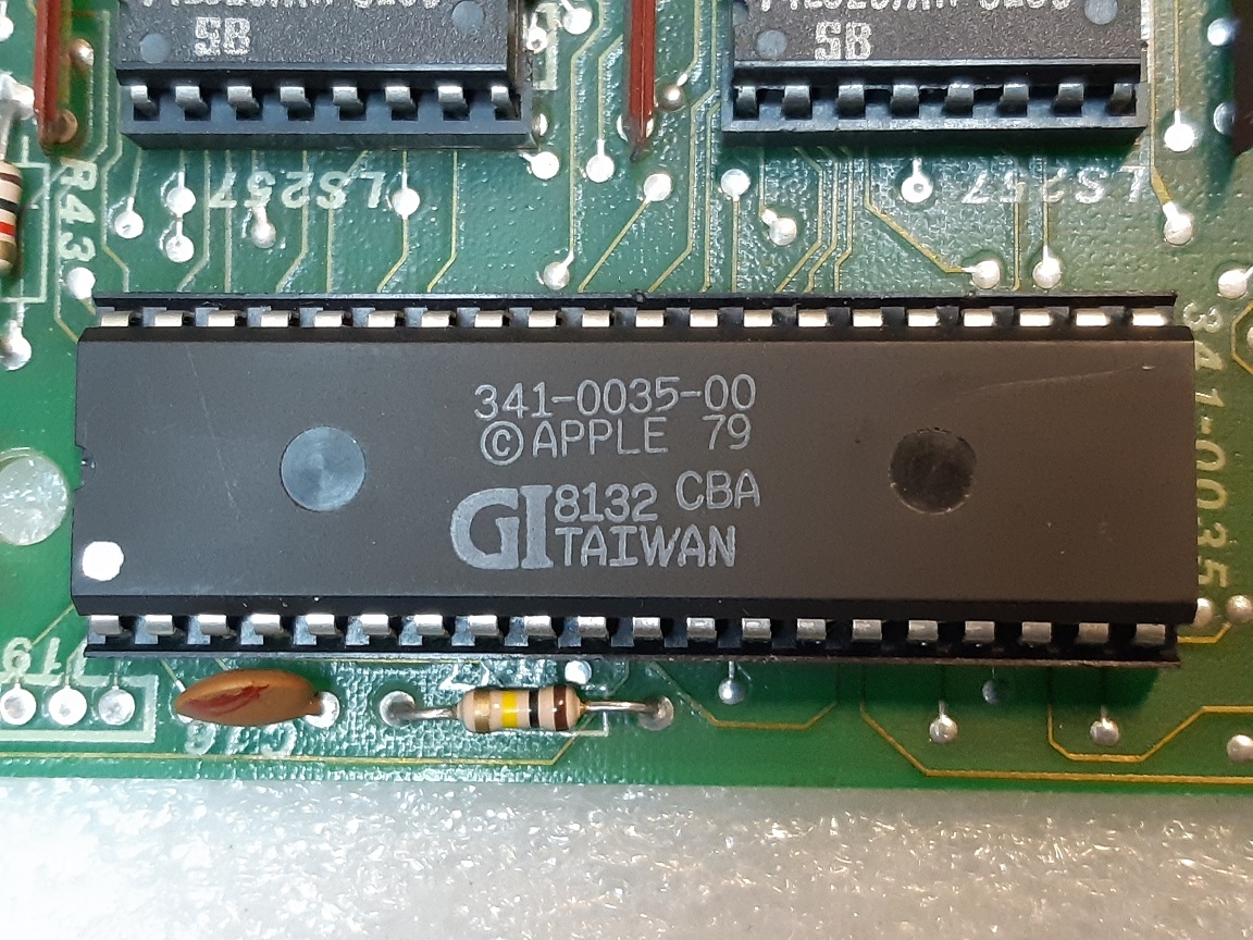
There is one problem left, the keyboard is not working properly , keys 1,Q,S,X,3,6 and 9 does not work. . All these keys are connected to Y1 in the keyboard. The separate key contacts are OK and the connection Y1 from the keyboard to pin 18 on the keyboard controller 341-0035 is OK. All other keys are OK.
Maybe its the 341-0035 thats defect. There is some information that Apple IIe , IIc and III has the same KB controller ? https://kb.pocnet.net/wiki/Apple_Chip-Bezeichnungen
Is it safe to test the Apple /// with a KB controller from Appple IIe? Will it work??
/Bengt
We don't really have a good replacement option for the keyboard controller. Its something that we need someone to make up an alternative either using a microcontroller or maybe using the KR3600 pro.
There has been some dicussion on the Apple3 facebook group regarding the micro controller option, not to sure how far this has gone. Maybe you can join that and have a search for keyboard controller.
The other option would be something like this:
https://stardot.org.uk/forums/viewtopic.php?f=45&t=12875&sid=b0d376b088e1102437e3b43026eff23c&start=120
/Rob
Hello again. I have not done anything to my Apple III for some time but no I´m trying to fix it again.
The problem is that the keyboard will not work. Only 1,Q,S,X and 3,6,9 on the keypad is defect. i get the following result when testing with Apple /// dealer test.
Apple /// dealer test
Apple /// dealer test
Number 1 key on the key pad is working but not on the keyboard. everything else in the Apple /// dealer test is OK.
New KB encoder
A year ago I was able to find a new encoder and it worked for one day but now the same problem. Now I dont know if the problem is in the KB encoder or other parts. Is something on the MB destroying the KB encoder? The tracing Y1 from the keyboard to pin 18 on 341-0035 is OK. I have reseated the encoder and the two 74LS257.
I recently found out that its possible the buy a new encoder (https://jcm-1.com/product/jcm-universal-keyboard-encoder/) and thats really great. I will get one of these but before I put it in it would be good to know if its something else on the MB thats defect.
Im greatful fore any advice. Thanks.
Twice the exact same issue, though the replacement chip did briefly work, that's certainly either an extreme coincidence - or a sign of another defect.
I would double check that Y1 doesn't have a short circuit to any other signal or voltage rail. The keyboard connector also has 5V and ground pins, to drive the light bulb - so it's not impossible that one of the keyboard matrix signals might get overloaded. Indeed, Y1 is on pin 2 of the keyboard connector - and pin 3 is Vcc (5V) - right next to it. So, yeah, that's at least a possibility...
Use your multimeter to measure the resistance from pin 2 to pin 3 on the keyboard connector (both on the mainboard, and also on the keyboard/cable itself - if the keyboard was unplugged).
If that does not show any short circuit, I would probably also do another test: remove the keyboard encoder chip and then use a high value resistor (like 100KOhm) to pull the Y1 signal to ground - and check the voltage level on the Y1 pin (with the machine/mainboard powered and no key pressed). Then repeat the test using the 100K resistor to pull Y1 to 5V. If there was any short circuit, the current through the 100K resistor will not be strong enough to pull the Y1 signal high/low. Without the keyboard encoder chip (and no key pressed), the Y1 signal should not be connected to anything, so any pull-up or pull-down resistor should be strong enough to change its voltage level.
That original chip (AY-5-3600-PRO) is unobtanium. Thankfully Joe's Computer Museum has a modern replacement...
https://jcm-1.com/product/jcm-universal-keyboard-encoder/
One last question: the fact that Y 1 is defect but the "1" key one the keypad is working: Does that prove that the fault must be in the KB or connections between KB and the encoder. Do I have to look for defects after the 341-0035 chip?
I will order new 341-0035 from Joes computer museum but the cause of this defect encoders has to be fixed. More information later
I don't think you should order any more encoders and I am willing to bet that you already have 2 good ones.
The most likely problem is those keys are simply not making contact when you press them. I had the same issue with my Apple IIe keyboard with a few keys. To fix them I removed their caps and sprayed pure isopropanol inside and moved their stems up and down as well as side to side a few dozen times. Isopropanol doesn't conduct electricity, so you can do it while the computer is on and see when they start working again.
Looking at your pictures I would also resolder them. Start with the ones that are not working.
The "1" on the keypad does not share the Y1 line - it's on the Y5 line. Since you say exactly the keys "1" (main keyboard), Q, S, X and the keypad's 9,6,3 are not working, while other keys are all working, it is basically guaranteed to be an issue with the Y1 line - as you already analyzed. The chances of exactly those 7 keys individually failing with contact issues, while everything else works are negligible.
The Apple /// service manual also confirms the keyboard matrix, mapping exactly those keys to the Y1 line:
AppleIIIKeyboard2.png
So, something is up with the Y1 line. It's either interrupted (connector or trace without proper contact), it's stuck (short circuit to something else) or otherwise the keyboard encoder is dead (and not driving the Y1 line any longer). Still, before ordering I would double and tripple check the connections. Also measure resistance. It'd be ideal if you had access to an oscilloscope, of course. You could check if the encoder chip is properly pulsing the Y1 line...
Here's another "poor man's test" (not owning an oscilloscope :) ) you could try. Remove the encoder chip. Take one of the presumably dead encoders and bend pin 18 upward and reinsert the chip into its socket (so now pin 18 = Y1 no longer has contact). Instead, make a temporary short circuit between the socket's pin 18 and 17 (the Y0 line). If pressing "1" now registers as "A", pressing "Q" registers as "Z" etc (see table above), then you confirmed that it's indeed the encoder's Y1 pin which is dead (and driving the keyboard's Y1 line by the encoder's Y0 signal works). But of course you should first the potential issues you showed above (copper wires and bad solder points which could cause issues).
Oh yeah, it's definitely the Y1 line!
I would start by removing the encoder chip and checking the resistance between Y1 (pin 18) and X1 (pin 39) when Q is pressed and when it's not. It should be infinite when it's not pressed and whatever the value of those resistors is when pressed.
I would also remove the plastic casing of the encoder chip's socket and check what is happening with its contacts, especially the one holding pin 18. Sometimes they get pushed down and don't make a good connection.
Keyboard Logic.jpg
Although I agree that Y1 is the most likely, double check the -12 volt power-supply at pin 27 too.
The encoder logic only requires +5 volts, but the internal PROM also requires -12 volts for reliable comparator operation. From experience with PROMs that use dual power supplies (eg: 2708 EPROMs) a hairline crack in the -12 volt supply can cause apparently-good / partially-bad operation, where a few arbitrary ROM locations don't work...just by chance.
Admittedly, the Y1 theory is a more probable cause...but it costs nothing to verify -12 volts at pin 27.
Hello and thank You all for helping me with this A III KB.
I have cleaned the backside of the KB ( IPA and toothbrush) and resoldered the bad solderings.
The Voltage on pin 27 is -12.38 V, pin 30 4.72 V.
The resistanse between pin 18 and 40 ( Y1-X0) on the encoder ( KB connected) is infinite when open, 48 ohm when i press "1"
Used a oscilloscope on pins Y0, Y1 and X0. measured with no key pressed and when I used "1" and "ESC". Se pictures below.the scope was on DC, 50 us/div and 5V/div. Zero levels for channel 1 (X0) and 2 in first picture. I dont really know how to analyze these results. i need some help with that.
Grounded_B.jpg
x0_y0_no_keyB.jpg
x0_y0_1B.jpg
x0_y0_escB.jpg
x0_y1_no_keyB.jpg
x0_y1_1B.jpg
x0_y1_escB.jpg
If the encoder is bad, maybee I have to remove the socket and check under it.
Greatful for any comments and help.
Ok, so there are few things that I find very strange compared to my NKDB-931, which is an encoder from an Apple II+ that I have adapted to work in my Apple IIe.
1. Your X and Y baselines are all over the place even when no key is pressed. On mine all the X’s and all the Y’s are always at the same baseline.
2. When you press 1, your entire X0 moves down and goes completely negative. On mine the X never moves when a corresponding key is pressed. Instead it’s the Y that moved up to completely cover it.
From what I can tell your only example that corresponds to how it should be is the X0 and Y0 behavior for when you press and release ESC. All the other X and Y's should behave like this. Here is how every single X and Y looks like on mine when no key is pressed. X is yellow, Y is blue, both channels are centered at 0V.
Newfile1.png
If I press the corresponding key, the blue simply covers the yellow perfectly. Pressing other keys do cause the yellow to move down just a tiny bit, maybe by about 0.1V, but definitely not by 5V like in your case.
So one thing I suggest that you do next: check the oscillogram of each X and each Y with no key pressed. They should all be sitting at the same baseline. From what I can tell from your pictures so far: your Y1 is sitting way below Y0 when no key is pressed. Is it the only one like this and what is pulling it down? Is it something inside or outside the chip?
I’ve discovered that it’s a lot easier to test it in the computer, but to be able to disconnect one or more individual pins. This is why I use a DIP40 intermediate socket like the one bellow between the original socket and the chip. It allows me to remove and put back any number of pins, so when I put the chip they will not make contact. If you don't have exactly a DIP40, you can break up a few smaller sockets of this type and use the individual pieces.
pctdetail.823-009.1.jpg
Attached is a measurement from my Apple ///. The one thing we got wrong above is the fact that the Y signals are inputs - it's the X signals which are the outputs. That indeed reduces the chances of Y1 being damaged by a short circuit. The X-outputs would suffer if a line was stuck to ground or 5V. But inputs don't care (well, as long as the voltage was within the allowed range of the input pin, of course).
The way the encoder works: the Y-inputs have weak pull-down resistors and are normally at a negative voltage level (slightly rippling along between -5V and -7.5V). The X-lines are briefly pulsing with +5V one by one. So the encoder registers a keypress when an Y-input changes its voltage level from a negative level to +5V. Interesting that they were indeed using a negative voltage and such a high voltage difference (about a 12V difference between "no key" vs "key pressed"). Somehow seems unnecessary - using 0 vs 5V would have been enough more than enough for the short keyboard cable (and that's what the modern replacement now does, as I understand it).
However, looking at your scope measurement suggests that your Y1 signal is stuck at -12V. If that was the case, then it indeed looks like a defective encoder chip. The chip is using internal pull-down resistors. It seems the pull-down resistor of Y1 has gone short-circuit and forces Y1 to be stuck at full -12V now. Hence, the +5V pulses from the X-outputs are unable to change the voltage level, when any of the keys is pressed.
AppleIII_Y1_signal_key_pressed.png
AppleIII_Y1_signal_no_key.png
If Y1 was shorted to -12V, you should see this pulse when you press 1 on the -12V rail as well:
x0_y1_1B.jpg
It's definitely being pulled down more than the others, but I don't think is being pulled down that hard. I think at this point it's important to determine if it's being pulled down inside or outside the chip. Easiest way to check is to disconnect Y0 and Y1 from the motherboard and see if Y1 is being pulled down harder than Y0 on the chip.
Yes, it is not a dead short - but it's being pulled to -12V way to hard. Even this photo of X0 vs Y1 (with key "1" pressed) shows that the X0 output is pulled to -12V and the pulses are merely making it to about 0V. The pulses on the X-ouputs must be +5V. Something is pulling the Y1 line to -12V so hard, that the X-outputs are unable to overcome the load and drive the signal to a positive level.
X0_overloaded.png
It's impossible to tell how hard it's being pulled down, without knowing how hard it's being driven up. The only way to tell is to hookup a potentiometer between the Y1 and +5V and see what kind of pull-up resistance would bring the Y1 baseline to the Y0 level, being careful not to go below a couple of hundred ohms of course. If it's not too hard, this could be a potential fix.
Or maybe with some luck it's not internal to the chip at all.
20221127_081413c.jpg
20221127_081451c.jpg
i have tested all combinations between X 0-7 and Y 0-9. All are working except Y1.
example: X0Y3 both zero lines at the middle, 5V, 50 us /div
X0_Y3_0c.jpg
X0_Y3_3c.jpg
All other combination are OK except Y1.
Voltage on pin 27: -12.45V on pin 18(Y1) - 12.24 V. No short between pin 18 and 27.
Two encoder chips give the same defects regarding the Y1 matrix, the primary fault must be outside the encoder chip. The PSU was defect when I got the AIII so maybee that has destroyed the first encoder. but the PSU was reparied before I put in the second encoder.
Can't make that determination with certainty just yet. Remove the encoder chip and with the power off measure the resistance between Y0 and -12V (pin 17 and pin 27 on the socket) and then between Y1 and -12V (pin 18 and pin 27 on the socket). If the Y1 resistance if much lower than the Y0 one, then yes, the problem is outside the chip.
Make sure to short them just before you measure the resistances just in case.
I have measured the resistans between pins
this encoder original encoder
17-27 9.4 Mohms 15M
18-27 2.3 kohms 1.8 kohms
19-27 9.8 Mohms 16 Mohms
20-27 9.9 Mohms 15 Mohms
Difference between kohms and Mohms
The question is what is destroying the encoders?
Those are the resistances of the removed chips, right? If yes, they are definitely damaged. Btw, whenever you measure resistance between pins of a chip with a multimeter like yours, you should always measure it one way, then reverse the leads and measure it again.
You also need to measure the resistances on the socket itself with the encoder chip removed. All the Xs and Ys on the empty socket should be infinite to ground, infinite to +5V and infinite to -12V, and I even think they should all be infinite to every single pin on the socket.
Yes resistance on removed chip.
Checked continuity between 0, +5, +12 and -12v to all x and Y: No continuity.
Even checked capacitor C16 and C22:OK (on the board). R47 OK.
Also checked continuity between encoder socket pins on the backside and pins on the encoder when seated..
20221127_154403b.jpg
No, don't remove the entire socket, just lift its plastic casing and check underneath it. On my Apple II+ inside one of the sockets I found a broken piece of a chip's leg stuck between the pins. It can be lifted like this and put right back. This picture is from my Pravetz 82, but your socket is similar.
20221125_123112.jpg
I can't really see anything unusual from the pictures, except for what you have noticed already. There is one more thing you could try though:
So we know for sure that both chips have been damaged most likely by the same cause. The damage has manifested itself as an internal resistance between Y1 and the -12V rail of 1.8k on the original encoder and 2.3k on the replacement. Also as a result of the damage they no longer detect a key press on Y1 of the matrix.
My idea is to use a pull up resistance between Y1 and the +5V rail and bring the Y1 baseline to the same level as the healthy Ys, maybe even higher. If the damage has not affected the pulse detection circuity of the Y1, then it should be able to detect a key press once the baseline is not so low and the pull up resistance will help to drive it higher when a key is pressed. If however Y1 goes right into a transistor that has been damaged, it's not going to work. The datasheet has all Ys going into a 10-bit comparator as a block.
How to do it: you will need to attach a 10K potentiometer between Y1 and +5V. Make sure its resistance it set to 10k. Then set up your oscilloscope so that both channels have no vertical offset and attach channel 1 to Y0 and channel 2 to Y1. When you turn on the computer you should still see the Y1 baseline way below Y0. Then slowly start decreasing the resistance of the potentiometer so that the Y1 baseline matches Y0. Then just press <1> and see if it detects it. If this doesn't work, you can go even a little above it.
I realize that this is a bit involved and you might not be comfortable with it. If that is the case, you should go right ahead and order a replacement.
Yes, you can cause damage if the potentiometer goes down to 0 ohms. To protect against this, you can use a 200 ohm resistor in series with the potentiometer. This way its range will be from 10.2K to 0.2K.
Testing the chip alone is pretty difficult and the setup will not be worth your while.
I think it's highly unlikely. This 74LS20 chip is not even connected to the encoder. The issue you are having is in the 10-bit comparator inside the encoder chip (top left):
Problem.png
I think the most likely cause was a short between Y1 and -12V or ground while a key was pressed and the Y1 was being driven up. Another possibility which MacFly already mentioned is a continuous short between Y1 and the +5V that drives the bulb.
My incorrect assumption, however, was that Y1 was an output. We've since corrected this, so Y are the inputs and X the outputs. So, Y1 would not suffer at all when there was a short circuit to ground or +5V. Any input voltage at Y between -7,5V to 5V is just normal, since that's what happens when pressing keys anyway. -12V might be outside Y's acceptable input range - but it even that may not be an issue.
There is a chance that both chips just happened to die the same way. It's also not uncommon for chips to show the exact same issues when dying: sometimes chips have weak spots, where they happen to fail more often (and you would need to know the exact layout of the internal chip design to tell why some element was more likely to fail first). It'd be interesting to compare this with other encoder chips which have died.
If both encoder chips came from the same batch, I would agree that there is a chance of both being defective to begin with. However looking at the pictures above they are more than a year apart, so I am pretty sure there was an external cause. And even though the Ys are inputs, they were not designed to be continuously at +5V, but only when a key is pressed and for the duration of a very short impulse. A continuous short to +5V could have caused some highly localized excessive heating to occur and result in damage, since the chip is trying to keep their baselines at around -7.5V.
Why would the chip designers pick a low-resistance value for the pull-down which could overheat at normal voltage input levels? The chip doesn't need any significant current to detect a high/low condition at its inputs. That would suggest a terribly dumb mistake in the chip design. And it would basically mean one shouldn't press a key too long (or too often), since it would otherwise affect the chip. I don't believe in such dumb mistakes.
It's not going to be the pull down resistor that would overheat. Comparators are complicated and contain many active elements: https://sound-au.com/articles/comparators.htm, but without this one's schematics it's not really possible to tell.
Also look at the area under the oscillogram when a key is pressed and compare it to the one when it’s not. This difference in area is proportional to the heat that would need to be dissipated. Even if all 7 keys of Y1 are pressed and held down continuously at the same time, the area is still not even half of what it would be compared to a continuous +5V. For a single key being held down continuously it's absolutely negligible.
Not only that, but now we know for sure that when a key is pressed the Ys are not being driven that hard to +5V, since it cannot even overcome this new resistance of 1.8k that has appeared between Y1 and -12V. A short to +5V would drive it much harder. If the baseline is being kept at a particular level by some active components, then they would have to work much harder to drive it down.
I fully realize that I am speculating here, but my point is simply that it's a valid possibility.
Hi CVT and MacFly. Thank You for Your interest in this complicated problem. Unfourtunatly this is far beyond my knowledge regarding computers and electronic components..
I'm very greatful that You are helping me. Inspected the KB backside more. Its obvious that Q9 and C71 has been replaced before I got this A III.
20221130_062858.jpg
20221129_225022.jpg
Q9 delivers the voltage KVCC to the KB lamp that was broken.
q9c71.png
I dont know if this could be of importance for the broken encoders.
The KB PCB looks OK but maybe I have to remove the KB connector and look under it on the MB??
20221130_063155.jpg
These usually hold much tighter than the IC sockets.
key Q pressed
KB_Q.png
Key Esc pressed
KB_Esc.png
Key Tab pressed
KB_Tab.png
Y1 channel is -12 V and thats the problem. I will do the test that CVT suggested to pull up the Y1 channel to the same level as Y0
A variabel resistor was connected between +5 volt and Y1.
The Y 1 line was elevated to - 8v.
DS1Z_QuickPrint7.png
When I pressed Q the picture is as this
DS1Z_QuickPrint8.png
Y1 elevated to - 7 volt
DS1Z_QuickPrint9.png
Q pressed:
DS1Z_QuickPrint10.png
Y1 = -6 volt
DS1Z_QuickPrint13.png
Q pressed:
DS1Z_QuickPrint14.png
Nothing happens on the screen so it not working.
Strange that Y1 is stuck to -12 v. no connection between Pin Y1 and 12 v rail.
Try lifting it up, so that when it's pressed it's higher than 4V. You see the healthy Ys are getting detected at 5V. If its barely at 1V when pressed, I don't think it has a chance of being detected.
I lifted it up to 2 v :
DS1Z_QuickPrint30.png
Q pressed:
DS1Z_QuickPrint31.png
+3 V
DS1Z_QuickPrint32.png
Q pressed
DS1Z_QuickPrint33.png
sorry but its not working. No Q on the screen.
i have got the new encoder but I´m not sure that its safe to connect it.
Yes, I see what is happening. Too bad.
Nothing is safe when it comes to retro computers, but who cares - they are not mission critical for anything. Take chance!
That being said, make sure Y1 with the new encoder sits at the same level as the rest of the Ys.
Thanks CVT for Your comments.
A last test before I switch to the new encoder. I bent out the pin from Y1 on the chip and connected the scope to both the pin and socket.
b2.jpg
On the oscillocope the channels are:
1: yellow X0
2: green X1
3: magenta Y0 pin on the chip
4: blue Y0 pin on the socket
DS1Z_QuickPrint35.png
Yep, the Y1 is damaged internally for sure.
__________________________
I finally put in the new KB encoder from jcm-1.com and its working perfect
jcm2.jpg
The tracing from the encoder is quite different.
DS1Z_QuickPrint7.png
DS1Z_QuickPrint10.png
DS1Z_QuickPrint11.png
But the keyboard is working perfect.
20230226_170306.jpg
20230227_213805.jpg
Its now working for the first time since I bought it six years ago.
Thank You all for Your help with this A ///.
Thank You Joe Strosnider at jcm-1.com for making this new KB encoder.
Oh yeah, this PIC microprocessor doesn’t have to run at 100 kHz like the original encoder, but it can go as high as 32 MHz. In terms of sheer processing power it's about 10 times faster than the main CPU on your Apple III, so as a keyboard encoder it’s just forget about it!
Most of the embedded and IoT type processors used on the modern designed upgrades and products for vintage computers have processors in them that are at least several times faster than the 2MHz 6502B in the Apple ///.